Procedure
DC fan motor of the indoor unit (control chip is installed in the motor):
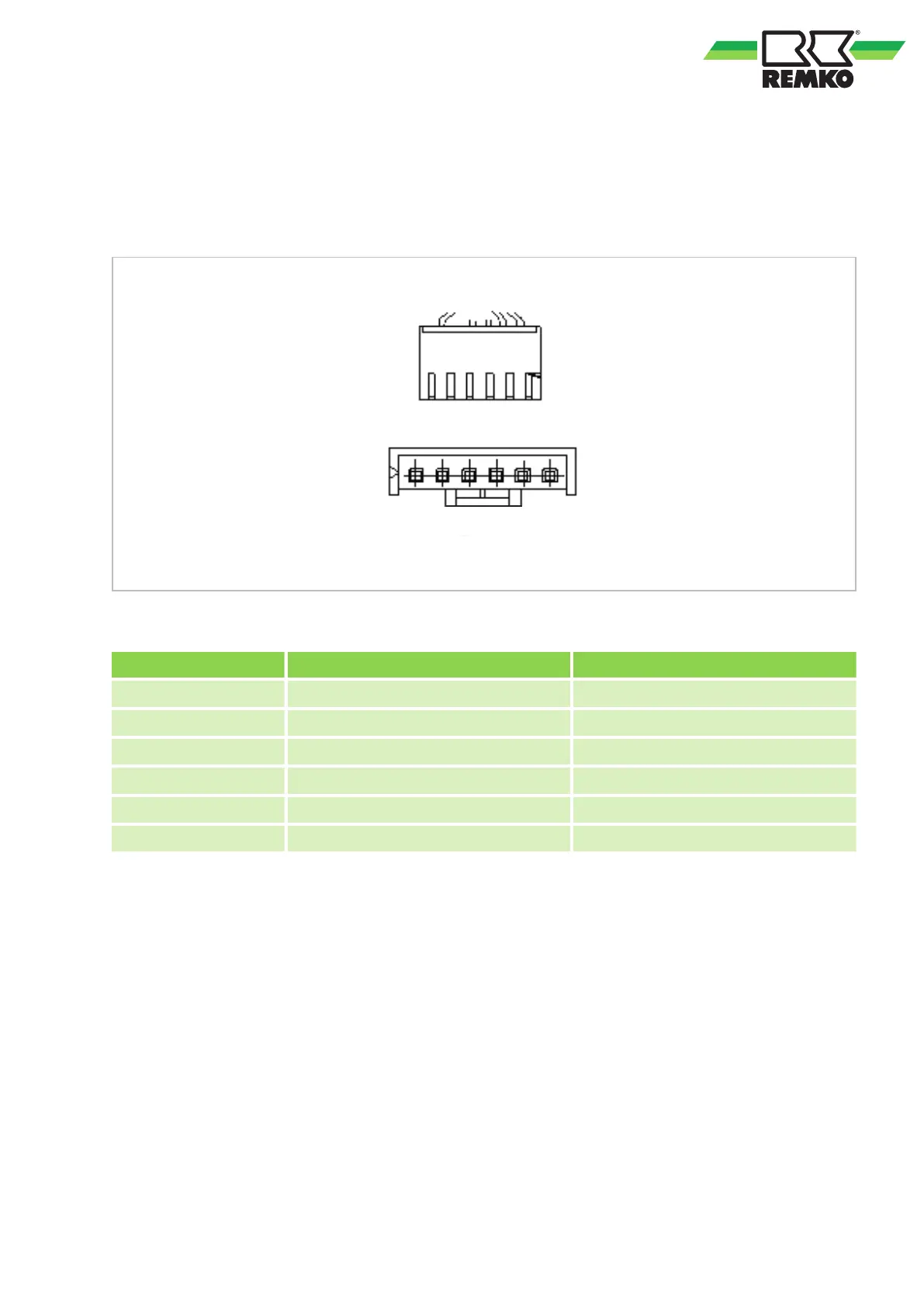
Switch on the voltage to the unit. In standby mode, measure the unit between terminals 1-3 and 4-3 of the
connector plug. Check the measured values against those listed in the table below
. If these differ, there is a
problem with the control board and it must be replaced.
Fig. 53: Motor measurements
Terminal Colour Voltage
1 Red 280V~380V
2 --- ---
3 Black 0 V
4 White 14-17.5V
5 Yellow 0~5.6V
6 Blue 14-17.5V
DC fan motor of the outdoor unit (control chip is installed in the motor):
Measure the resistance between terminals 1-3 and 4-3. This should be roughly identical. If the resistance
deviates significantly, assume that the motor is defective and must be replaced.
49