Renesas RA Family EK-RA4M3 v1 – User's Manual
R20UT4803EG0101 Rev 1.01 Page 13 of 29
Jan.06.21 Nov.09.20
5.1 Power
The EK-RA4M3 kit is designed for +5 V operation. An on-board Low Dropout Regulator (LDO) is used to
convert the 5 V supply to a 3.3 V supply. The 3.3 V supply is used to power the RA MCU and other
peripheral features.
5.1.1 Power Supply Options
This section describes the different ways in which EK-RA4M3 kit can be powered.
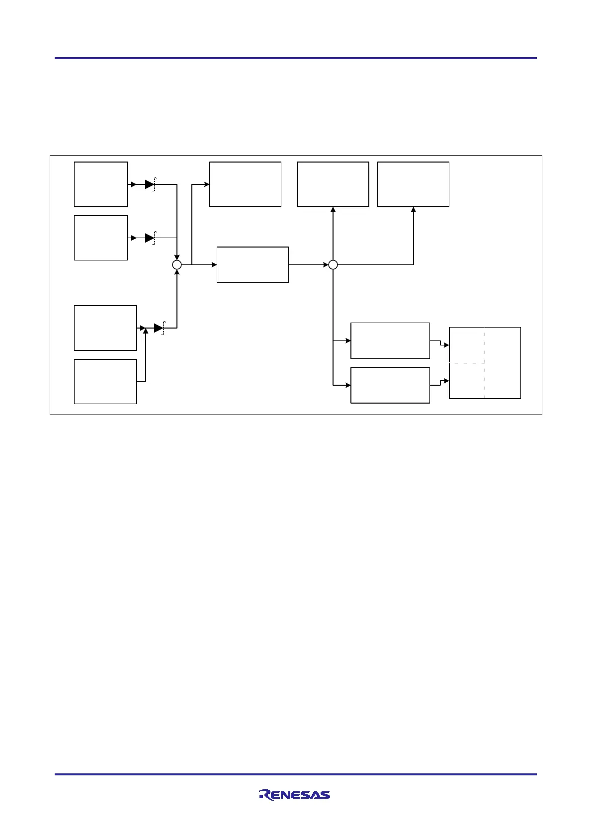
Figure 8. Power Supply Options
5.1.1.1 Option 1: Debug USB
5 V may be supplied from an external USB host to the USB Debug connector (J10) labelled DEBUG on the
board. Power from this source is connected to the Main System 5 V Power. Reverse current protection is
provided between this connector and the Main System 5 V Power.
5.1.1.2 Option 2: USB Full Speed
5 V may be supplied from an external USB host to the USB Full Speed connector (J11) labelled USB FULL
SPEED on the board. Power from this source is connected to the Main System 5 V Power. Reverse current
protection is provided between this connector and the Main System 5 V Power.
5.1.1.3 Option 3: 5V Test Points
5 V may be supplied from an external power supply to test points on the board. TP7 (5 V) and TP9 (GND)
are loop-style test points, and TP5 (5 V) and TP6 (GND) are large via style test points. The two types of test
points are electrically equivalent, and both are provided for user convenience. Power from this source is
connected to the Main System 5 V Power. Reverse current protection is provided between the 5 V test points
and the Main System 5 V Power.
5.1.2 Power Supply Considerations
The on-board LDO regulator which supplies +3.3 V has a built-in current limit of 2.0 A. Make sure the total
current required by the RA MCU, any active on-board features, and any connected peripheral devices does
not exceed this limit.
Note: The total current available from a typical USB host is 500 mA maximum. Depending on the
configuration of the kit, multiple power sources may be required.
5.1.3 Power-up Behavior
When powered, the white LED near the center of the board (the “dash” in the EK-RA4M3 name) will light up.
For more details on initial power up behavior, see the EK-RA4M3 Quick Start Guide.
5 V to 3.3 V
Voltage
Regulator
Option 1:
Debug USB
(J10)
Option 3a:
TP5 and TP6
3.3 V Voltage
Measurement:
TP8 and TP10
MCU Current
Measurement
(R3) TP1 and TP3
Main System
3.3 V Pow e r
RA
MCU
Main
Power
USB
Power
Option 2:
USB FS
(J11)
Option 3b:
TP7 and TP9
MCU Current
Measurement
(R2) TP2 and TP4
Main System
5 V Pow er
 Loading...


