EasyManua.ls Logo

Renesas EK-RA4M3

Renesas EK-RA4M3
35 pages
To Next Page IconTo Next Page
To Previous Page IconTo Previous Page
Loading...
Renesas RA Family EK-RA4M3 v1User's Manual
R20UT4803EG0101 Rev 1.01 Page 21 of 29
Jan.06.21 Nov.09.20
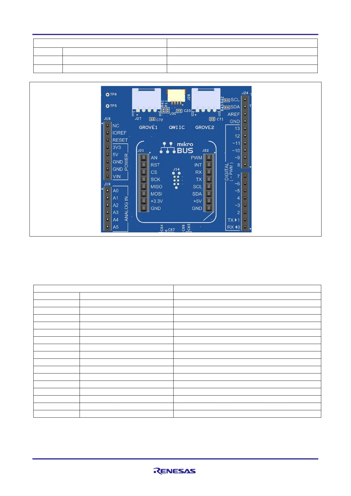
Arduino Compatible Connector
EK-RA4M3
Pin
Description
Signal/Bus
J24-9
I2C_SDA
P511 (SDA1)
J24-10
I2C_SCL
P512 (SCL1)
Figure 14. Arduino Uno Connectors
5.3.5 MikroElektronikamikroBUS Connector
In the center of the System Control and Ecosystem Access area is a mikroBUS compatible connector
interface. This interface is compliant with mikroBUS Standard Specifications revision 2.00.
Table 16. mikroBUS Connections
mikroBUS Connector
EK-RA4M3
Pin
Description
Signal/Bus
J21-1
AN (Analog)
P000 (AN000)
J21-2
RST (Reset)
P115
J21-3
CS (SPI Chip Select)
P205 (SSLA0)
J21-4
SCK (SPI Clock)
P204 (RSPCKA)
J21-5
MISO
P202 (MISOA)
J21-6
MOSI
P203 (MOSIA)
J21-7
+3.3 V
+3.3V
J21-8
GND
GND
J22-1
PWM
P408 (GTIOC6B)
J22-2
INT (Hardware Interrupt)
P409 (IRQ6)
J22-3
RX (UART Receive)
P100 (RXD0)
J22-4
TX (UART Transmit)
P101 (TXD0)
J22-5
SCL (I2C Clock)
P512 (SCL1)
J22-6
SDA (I2C Data)
P511 (SDA1)
J22-7
+5 V
+5V
J22-8
GND
GND

Table of Contents

Related product manuals