Renesas RA Family EK-RA4M3 v1 – User's Manual
R20UT4803EG0101 Rev 1.01 Page 24 of 29
Jan.06.21 Nov.09.20
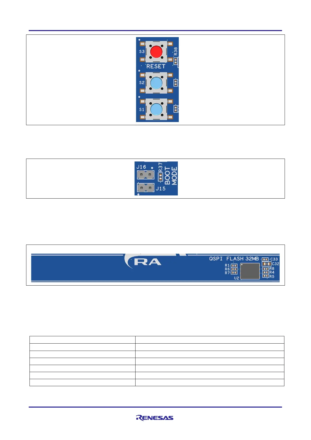
Figure 19. Reset and User Switches
5.5.3 MCU Boot Mode
A two-pin header (J16) is provided to select the Boot mode of the RA MCU. For normal operation, or Single-
Chip mode, leave J16 open. To enter SCI Boot mode or USB Boot mode, place a jumper on J16.
Figure 20. Boot Mode
Note: The RA MCU fitted to the EK-RA4M3 board may not contain the latest version of the on-chip boot
firmware.
6. Special Feature Access Area
The Special Feature Access area provides features specific to the RA4M3 MCU group such as Quad-SPI.
Figure 21. Special Feature Access Area
6.1 Quad-SPI Flash
Included on the EK-RA4M3 board is a Macronix 32 MB Quad-SPI flash memory (MX25L25645G). The
Quad-SPI flash (U2) connects to the QSPI peripheral on the RA MCU and defaults to standard SPI mode
initially. The Quad-SPI flash memory is enabled for XIP (Execute-in-place) mode directly after power-on.
Table 20. Quad-SPI Flash Port Assignments
Quad-SPI Signal Description
 Loading...


