Renesas RA Family EK-RA4M3 v1 – User's Manual
R20UT4803EG0101 Rev 1.01 Page 26 of 29
Jan.06.21 Nov.09.20
7.1 Breakout Pin Headers
The EK-RA4M3 board pin headers, J1, J2, J3 and J4, provide access to all RA MCU interface signals, and to
voltages for all RA MCU power ports. Each header pin is labeled with the voltage or port connected to that
pin. Refer to the RA4M3 MCU Group User’s Manual for details of each port function, and the EK-RA4M3
board schematic for pin header port assignments.
The placement of the breakout pin headers allows for a standard 2.54 mm (0.100”) center breadboard to be
placed on all four pin headers simultaneously. This can be used for prototyping and testing of custom
circuitry for use with the RA4M3 MCU.
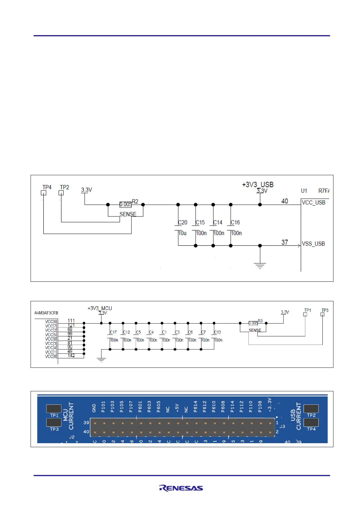
7.2 MCU and USB Current Measurement
Included in the Native Pin Access area are current measurement resistors and test points to measure the
MCU USB controller current and the MCU core power current.
The EK-RA4M3 board provides precision 5 mΩ resistors (Vishay, part number WSLP08055L000FEA18) for
current measurement of the main 3.3 V MCU power, and the 3.3 V USB MCU power. Measure the voltage
drop across these resistors and use Ohm’s Law to calculate the current. For convenience, TP1 and TP3 are
provided to measure the main 3.3 V MCU power, and TP2 and TP4 are provided to measure the 3.3 V USB
MCU power. See Figure 26 for the location of TP1, TP3, TP2 and TP4.
Figure 24. RA USB Current Measurement Circuit
Figure 25. RA +3.3 V Current Measurement Circuit
Figure 26. RA MCU Current Measurement
 Loading...


