Renesas RA Family EK-RA4M3 v1 – User's Manual
R20UT4803EG0101 Rev 1.01 Page 15 of 29
Jan.06.21 Nov.09.20
To configure the EK-RA4M3 board to use the Debug On-Board mode, configure the jumpers using the
following table.
Table 5. Debug On-Board Jumper Configuration
Target RA MCU MD connected to debug
Target RA MCU RESET# connected to debug RESET#
S124 Debug MCU in normal operation mode
Jumpers on pins 1-2, 3-4, 5-6, 7-8
Target RA MCU debug signals connected to the Debug
Interface
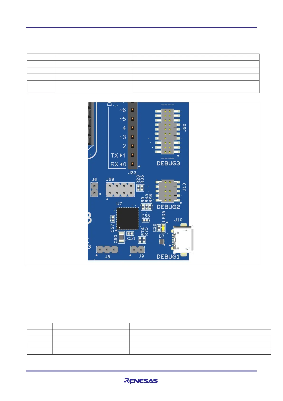
Figure 9. EK-RA4M3 Debug Interface
5.2.2 Debug In
One 20-pin Cortex
®
Debug Connector at J20 supports JTAG, SWD and ETM (TRACE) debug. One 10-pin
Cortex
®
Debug Connector at J13 supports JTAG and SWD. Either of these connectors may be used for
external debug of the target RA MCU.
To configure the EK-RA4M3 board to use the Debug in mode, configure the jumpers using the following
table.
Table 6. Debug In Mode Jumper Configuration
Target RA MCU MD connected to debug
Target RA MCU RESET# connected to debug RESET#
S124 Debug MCU is held in RESET
Jumpers on pins 1-2, 3-4, 5-6, 7-8
Target RA MCU debug signals connected to the Debug Interface
 Loading...


