Renesas RA Family EK-RA4M3 v1 – User's Manual
R20UT4803EG0101 Rev 1.01 Page 22 of 29
Jan.06.21 Nov.09.20
Figure 15. mikroBUS Connection
5.4 Connectivity
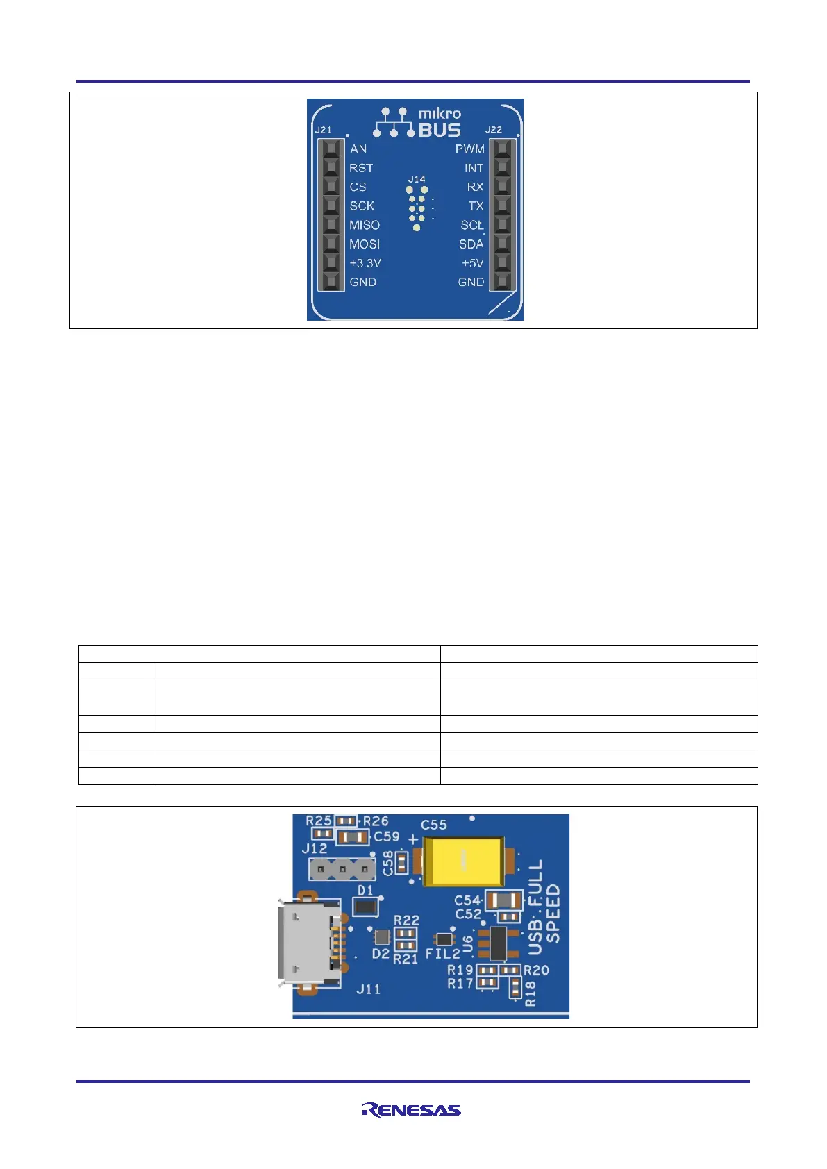
5.4.1 USB Full Speed
The USB Micro-AB connection jack (J11) connects the RA MCU USB Full Speed interface to an external
USB interface, allowing communications for testing and use of the RA MCU firmware. This connection can
be configured as either a USB Device or a USB Host interface.
For a USB Device configuration, set jumper J12 to pins 2-3, install a jumper on J15 pins 1-2, and configure
the RA MCU firmware to use the USB Full Speed ports in device mode. Power from an external USB Host
on this connection can be used to provide power to the EK-RA4M3 board.
For a USB Host configuration, set jumper J12 to pins 1-2, remove the jumper from J15, and configure the RA
MCU firmware to use the USB Full Speed ports in host mode. In this configuration, power to J11 is supplied
from U6. The total current available from U6 is 500 mA. Note that the input power sources must be
configured with enough power for both the EK-RA4M3 board and the USB Full Speed port in host mode.
Connect the included USB type-A female to micro-B male cable to J11. USB device cables or devices can be
connected to the USB Full Speed port using this cable.
Table 17. USB Full Speed Connector
+5VUSB (Host Mode)
P407/USB_VBUS = 2/3 of +5VUSB at J11
USB ID, jack internal switch, cable inserted
Figure 16. USB Full Speed Connector
 Loading...


