EasyManua.ls Logo

Renesas EK-RA4M3

Renesas EK-RA4M3
35 pages
To Next Page IconTo Next Page
To Previous Page IconTo Previous Page
Loading...
Renesas RA Family EK-RA4M3 v1User's Manual
R20UT4803EG0101 Rev 1.01 Page 16 of 29
Jan.06.21 Nov.09.20
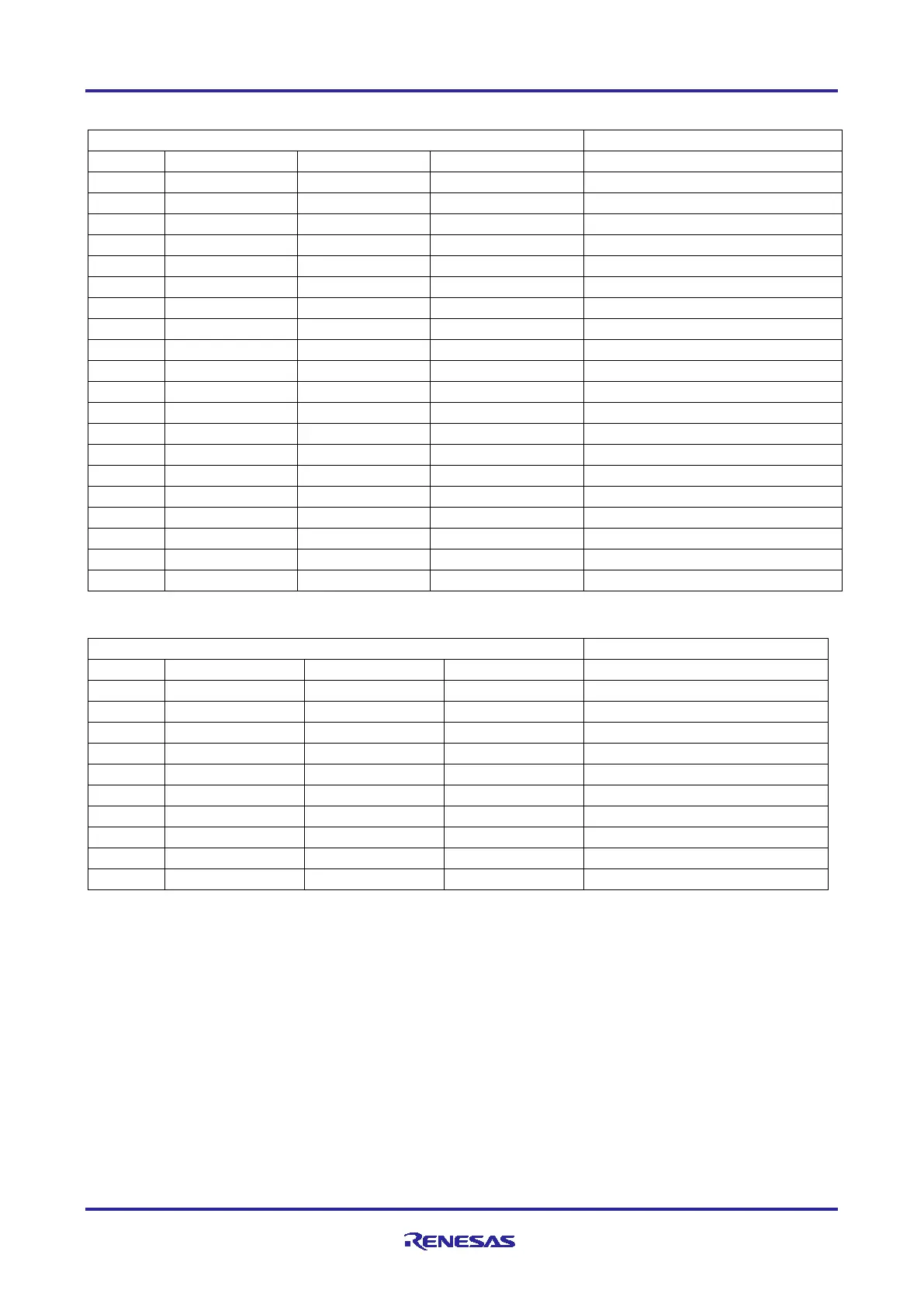
Table 7. JTAG/SWD/TRACE Connector
JTAG Connector
EK-RA4M3
Pin
JTAG Pin Name
SWD Pin Name
ETM Pin Name
Signal/Bus
J20-1
Vtref
Vtref
Vtref
+3V3
J20-2
TMS
SWDIO
N/A
P108/SWDIO
J20-3
GND
GND
GND
GND
J20-4
TCK
SWCLK
N/A
P300/SWCLK
J20-5
GND
GND
GND
GND
J20-6
TDO
SWO
N/A
P109/TDO
J20-7
Key
Key
Key
N.C.
J20-8
TDI
NC/EXTb
N/A
P110/TDI
J20-9
GNDDetect
GNDDetect
GNDDetect
GND (cut E30 to open)
J20-10
nSRST
nSRST
nSRST
RESET#
J20-11
N/A
N/A
N/A
GND
J20-12
N/A
N/A
TCLK
P214/TCLK
J20-13
N/A
N/A
N/A
GND
J20-14
N/A
N/A
TDATA0
P211/TDATA0
J20-15
N/A
N/A
GND
GND
J20-16
N/A
N/A
TDATA1
P210/TDATA1
J20-17
N/A
N/A
GND
GND
J20-18
N/A
N/A
TDATA2
P209/TDATA2
J20-19
N/A
N/A
GND
GND
J20-20
N/A
N/A
TDATA3
P208/TDATA3
Table 8. JTAG/SWD Connector
JTAG Connector
EK-RA4M3
Pin
JTAG Pin Name
SWD Pin Name
ETM Pin Name
Signal/Bus
J13-1
Vtref
Vtref
Vtref
+3V3
J13-2
TMS
SWDIO
N/A
P108/SWDIO
J13-3
GND
GND
GND
GND
J13-4
TCK
SWCLK
N/A
P300/SWCLK
J13-5
GND
GND
GND
GND
J13-6
TDO
SWO
N/A
P109/TDO
J13-7
Key
Key
Key
N.C.
J13-8
TDI
NC/EXTb
N/A
P110/TDI
J13-9
GNDDetect
GNDDetect
GNDDetect
GND (cut E30 to open)
J13-10
nSRST
nSRST
nSRST
RESET# (via J8)
Note: The Cortex
®
Debug Connector is fully described in the Arm
®
CoreSight
Architecture Specification.
5.2.3 Debug Out
The EK-RA4M3 board can be configured to use the S124 Debug MCU to debug target RA MCU on an
external board.
A yellow indicator, LED5, shows the visual status of the debug interface. When the EK-RA4M3 board is
powered on, and LED5 is blinking, this indicates that the S124 Debug MCU is not connected to a
programming host. When LED5 is on solid, this indicates that the S124 Debug MCU is connected to a
programming interface.

Table of Contents

Related product manuals