Renesas RA Family EK-RA4M3 v1 – User's Manual
R20UT4803EG0101 Rev 1.01 Page 19 of 29
Jan.06.21 Nov.09.20
The default setting of the Pmod 1 interface supports +3.3 V devices. Please ensure that any Pmod device
installed is compatible with a +3.3 V supply.
Pmod Type 6A Operation
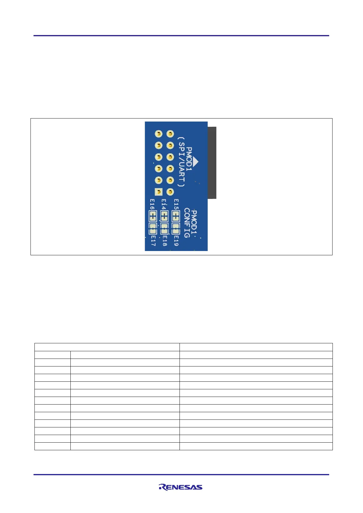
Pmod 1 can be configured to support proposed Pmod Type 6A connector specification supporting I2C
connections. There is also an alternate 5 V power source option. In order to configure Pmod 1 for Type 6A
operation, modify the trace cut jumpers as mentioned in Table 13. The trace cut jumpers are shown in Figure
12.
Note: Exercise caution while modifying power source trace jumpers, E16 and E17. Permanent
damage to the EK-RA4M3 board and/or connected modules may result.
Figure 12. Pmod 1 Trace Cut Jumpers
5.3.3.2 Pmod 2
A 12-pin Pmod type-2A connector is provided at J25, Pmod 2. The RA MCU acts as the SPI master, and the
connected module acts as an SPI slave device. This interface may additionally be re-configured in firmware
as several other Pmod types.
This Pmod interface supports +3.3 V devices. Please ensure that any Pmod device installed is compatible
with a +3.3 V supply.
Table 14. Pmod 2 Connector
GPIO / INT (slave to master)
GPIO / RESET (master to slave)
 Loading...


