Renesas RA Family FPB-RA2E1 v1 – User's Manual
R20UT4956EG0100 Rev 1.00 Page 10 of 24
Jul.23.21
4.3 Jumper Settings
Two types of jumpers are provided on the FPB-RA2E1 board.
1. Copper jumpers (trace-cut type and solder bridge type)
2. Traditional pin header jumpers
The following sections describe each type and their default configuration.
4.3.1 Copper Jumpers
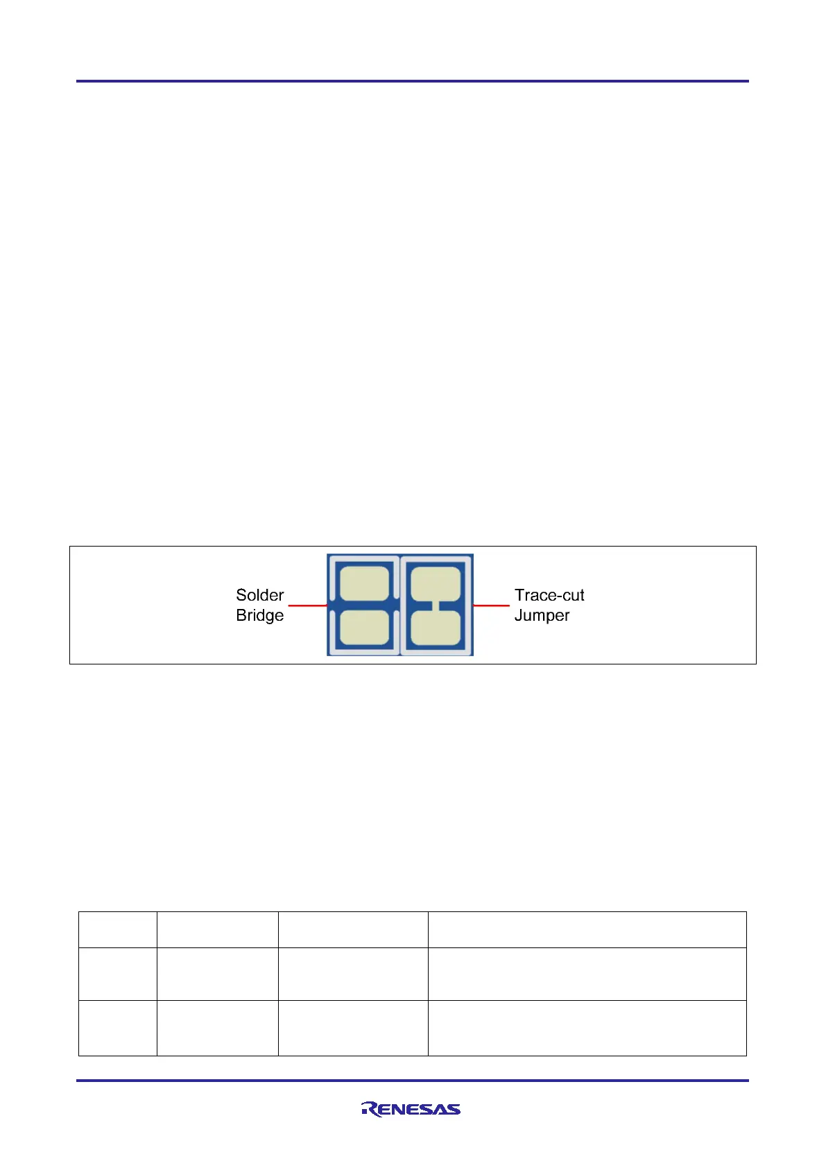
Copper jumpers are of two types, designated trace-cut and solder-bridge.
A trace-cut jumper is provided with a narrow copper trace connecting its pads. The silk screen overlay
printing around a trace-cut jumper is a solid box. To isolate the pads, cut the trace between pads adjacent to
each pad, then remove the connecting copper foil either mechanically or with the assistance of heat. Once
the etched copper trace is removed, the trace-cut jumper is turned into a solder-bridge jumper for any later
changes.
A solder-bridge jumper is provided with two isolated pads that may be joined together by one of three
methods:
• Solder may be applied to both pads to develop a bulge on each and the bulges joined by touching a
soldering iron across the two pads.
• A small wire may be placed across the two pads and soldered in place.
• A SMD resistor, size 0805, 0603, or 0402, may be placed across the two pads and soldered in place. A
zero-ohm resistor shorts the pads together.
For any copper jumper, the connection is considered closed if there is an electrical connection between the
pads (default for trace-cut jumpers.) The connection is considered open if there is no electrical connection
between the pads (default for the solder-bridge jumpers).
Figure 5. Copper Jumpers
4.3.2 Traditional Pin Header Jumpers
These jumpers are traditional small pitch jumpers that require an external shunt to open/close them. The
traditional pin jumpers on the FPB-RA2E1 board are 0.1” (2.54 mm) pitch headers and require compatible
2.54 mm shunt jumpers.
4.3.3 Default Jumper Configuration
The following table describes the default settings for each jumper on the FPB-RA2E1 board. This includes
copper jumpers (Ex designation) and traditional pin jumpers (Jx or CNx designation).
The circuit group for each jumper is the designation found in the board schematic (available in the Design
Package). Functional details for many of the listed jumpers may be found in sections associated with each
functional area of the kits.
Table 2. Default Jumper Settings
Jumper on pins 2-3
Debugger held in reset (RA2E1 MCU free-
(not fitted)
(shorted by E27)
 Loading...


