Renesas RA Family FPB-RA2E1 v1 – User's Manual
R20UT4956EG0100 Rev 1.00 Page 20 of 24
Jul.23.21
Table 13. Clock Crystal Part Numbers
Manufacturer and Part Number
ABRACON ABM8-20.000MHZ-10-B1U-T
ABRACON ABS06-32.768KHZ-1-T
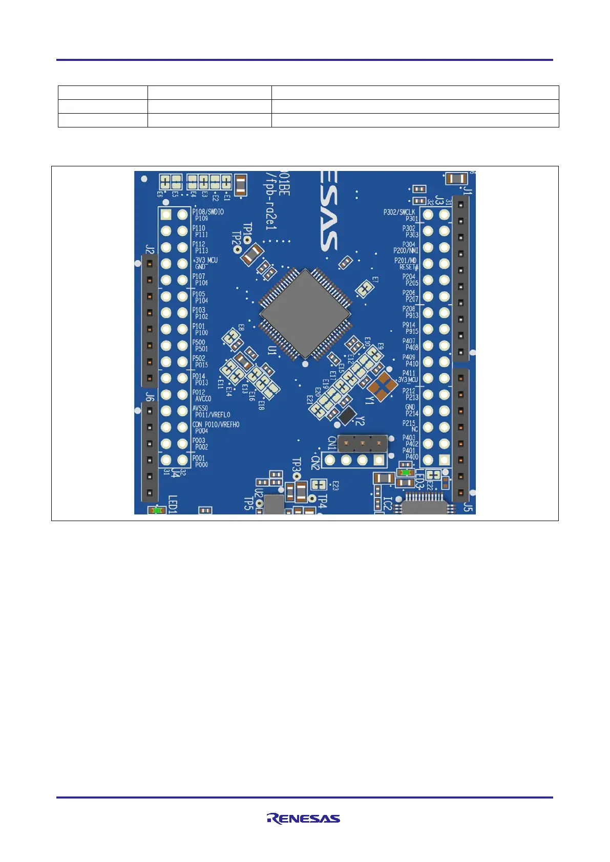
6. MCU Native Pin Access Area
Figure 17. Native Pin Access Area J3 and J4
6.1 Breakout Pin Headers
The FPB-RA2E1 board pin headers (not fitted), J3 and J4, provide access to all RA MCU interface signals,
and to voltages for all RA MCU power ports. Each header pin is labelled with the voltage or port connected to
that pin. Refer to the RA2E1 MCU Group User’s Manual for details of each port function, and the FPB-
RA2E1 board schematic for pin header port assignments.
The placement of the breakout pin headers allows for a standard 2.54 mm (0.100”) centre breadboard to be
placed on both pin headers simultaneously. This can be used for prototyping and testing of custom circuitry
for use with the RA2E1 MCU.
6.2 MCU Current Measurement
Included near the RA MCU is resistor R3 and test points TP1 and TP2 to measure the MCU core current.
Resistor R3 is 0 Ω (SMD 0805) as supplied. It should be removed in order to measure the current consumption
using an ammeter connected between TP1 and TP2.
Alternatively, it could be removed and replaced with a suitable low value resistor (such as 100 mΩ), and then
a voltmeter used to measure the voltage between TP1 and TP2. The current drawn by the MCU can then be
calculated using Ohm’s Law.
 Loading...


