Renesas RA Family FPB-RA2E1 v1 – User's Manual
R20UT4956EG0100 Rev 1.00 Page 15 of 24
Jul.23.21
5.3 Ecosystem
The Ecosystem connectors provide users the option to simultaneously connect several third-party add-on
modules compatible with two popular ecosystems using the following connectors:
1. Two Digilent Pmod™ (SPI and UART) connectors
2. Arduino™ (Uno R3) connectors
5.3.1 Digilent Pmod™
Connectors
5.3.1.1 Pmod 1
A 12-pin Pmod Type-2A (expanded SPI) and Type-3A (expanded UART) connector is provided at connector
PMOD1. The RA MCU acts as the SPI master, and the connected module acts as an SPI slave device. This
interface may additionally be re-configured in firmware as several other Pmod types.
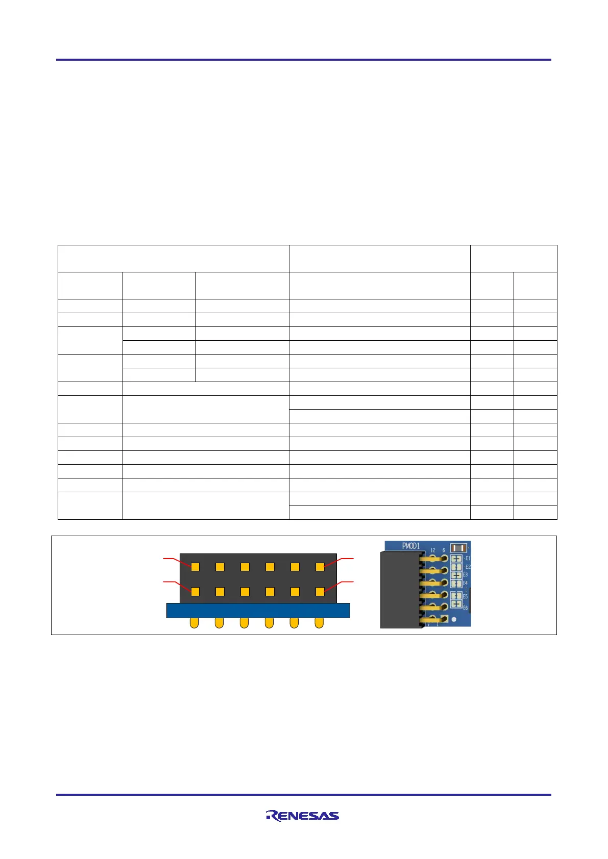
Table 8. Pmod 1 Connector
GPIO / INT (slave to master)
GPIO / RESET (master to slave)
Figure 9. Pmod 1
The default setting of the Pmod 1 interface supports +3.3 V devices. Please ensure that any Pmod device
installed is compatible with a +3.3 V supply.
Pmod Type 6A Operation
Pmod 1 can be configured to support proposed Pmod Type 6A connector specification supporting I
2
C
connections. There is also an alternative 5 V power source option. In order to configure Pmod 1 for Type 6A
operation, modify the trace cut jumpers as described in Table 8. The trace cut jumpers are shown in Figure
10.
Note: Exercise caution while modifying power source trace jumpers, E1 and E2. Permanent damage
to the FPB-RA2E1 board and/or connected modules may result.
 Loading...


