Renesas RA Family FPB-RA2E1 v1 – User's Manual
R20UT4956EG0100 Rev 1.00 Page 19 of 24
Jul.23.21
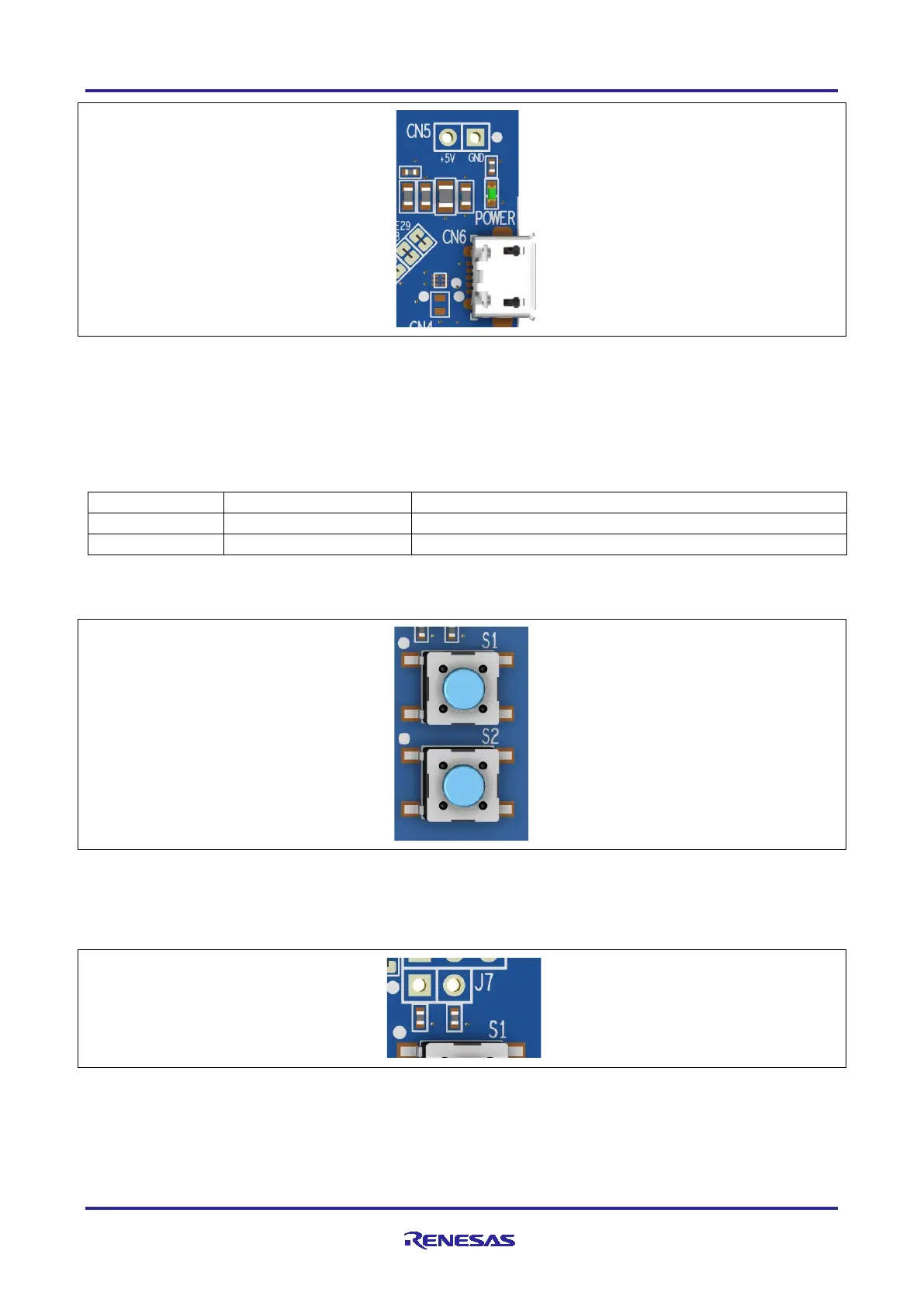
Figure 14. Power LED
5.4.2 User and Reset Switches
Two miniature, momentary, mechanical push-button type SMD switches are mounted on the FPB-RA2E1
board.
Pressing the reset switch (S2) generates a reset signal to restart the RA MCU.
Table 12. FPB-RA2E1 Board Switches
The User Switch S1 may be isolated from the MCU, so that the associated port can be used for other
purposes. To disconnect S1 from P205, trace cut jumper E24 must be open.
Figure 15. Reset (S2) and User Switch (S1)
5.4.3 MCU Boot Mode
A two-pin header (J7) can be fitted to select the boot mode (P201) of the RA MCU. For normal operation
(single-chip mode), leave J7 open. To enable SCI boot mode, place a jumper on J7.
Figure 16. Boot Mode Jumper (J7)
5.4.4 MCU Clocks
The option has been provided to fit RA MCU oscillator and sub-clock oscillator crystals, providing precision
20.000 MHz and 32,768 Hz reference clocks to the board.
 Loading...


