RH850/U2A 144pin 2. Jumpers, Connectors, Switches and LEDs
R20UT5089ED0101 Rev.1.01 Page 8 of 56
July 08, 2022
2.2 Connector Overview
The following table provides an overview of all connectors.
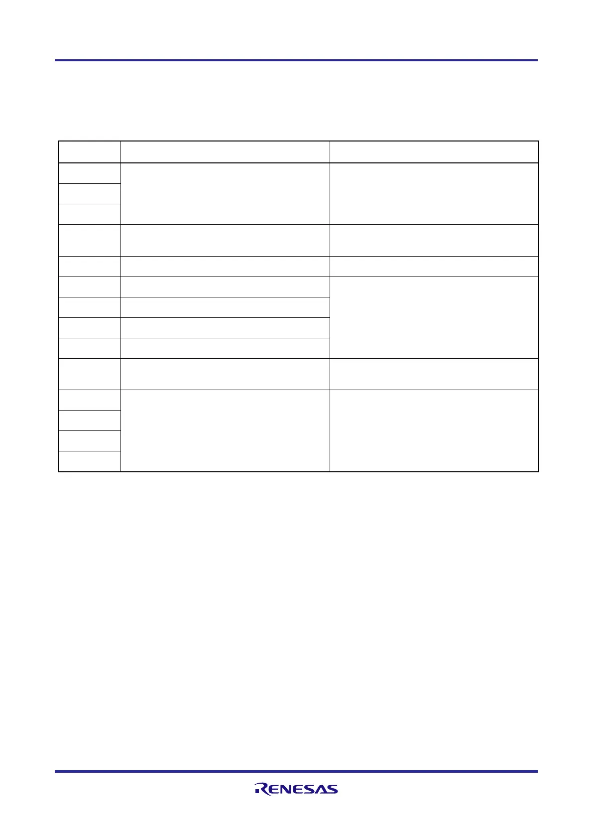
Table 2.2 Connector overview (cont'd)
Connector Function Remark
CN1 Main Board connectors refer to 7.1 Connectors to the Main Board CN1
to CN3
CN2
CN3
CN4 Debug connector refer to 5 Debug and Flash Programming
Interfaces and 7.2 Debug Connector CN4
CN7 Signaling LEDs pin header refer to 6.3 Signaling LEDs
CN8 GND for external power supply refer to 3.1 Board Power Connection,
connector CN11 is not assembled on the board
CN9 +5.0 V external power supply
CN10 +3.3 V external power supply
CN11 +1.12 V external power supply *
CN12 Pull-up/Pull-down pin header refer to 6.4 Pull-Up/Pull-Down Pin Header and
7.4 Pull-Up/Pull-Down Pin Header CN
CN13 Device ports connectors refer to 7.3 Device Ports Connectors CN13 to
CN16
CN14
CN15
CN16
Note: * Refer to 3.3 Device Core Voltage (VDD) Selection for further details about VDD voltage.
 Loading...