RH850/U2A 144pin 6. Other Circuitry
R20UT5089ED0101 Rev.1.01 Page 18 of 56
July 08, 2022
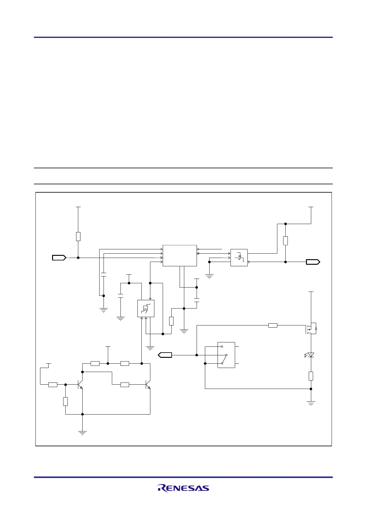
6.2 RESET Switch
The SW1 is used to issue a RESET to the device.
The SW1 toggle switch allows to activate the RESET in two different ways:
• SW1 in left '5-4 (ON)' position: temporary reset
Releasing the switch's lever returns the switch to its middle 'OFF' position and thus releases the reset.
• SW1 in right '5-6 ON' position: permanent reset
For reset release the switch has to be moved back manually to its middle 'OFF' position.
The left and right switch position is defined from the side of the part number marking, which
is highlighted with a red arrow in
Figure 6.3 Operation of RESET switch
.
The lighted red LED13 indicates that SW1 is "on", i.e. in position '5-4 (ON)' or '5-6 ON'.
Note
LED13 does not light up when RESET is asserted by any other means than SW1.
PUSH BUTTON FOR RESET
VCC up to resetz up
Min 3ms from
3.3V
P3V3
100n
TLC7701ID
3.3V
220n
2K2
P3V3
3.3V
SN74LV1T125DCKR
10K
NXP_BC847C
BSS84
P3V3
10K
56K
10K
750
3.3V
red
NXP_BC847C
3.3V or 5V
SYSVCC
10K
10K
P3V3
3.3V
10K
NKK_G19AP
4K7
VDD
P3V3
DNF/DNB
74LVC1G32SE-7
100n
1.12V
C74
R34
IC4
SW1
TR9
C81
R57
R56
LED13
R59
IC9
IC8
C92
R10
R52
TR8
R53
R51
TR7
R50
R49
3E3
RESET_IN
RESETZ
NC
RESET_IN
4
5
3
2
1
6
5
4
3
1
2
1
3
4
51
3
2
8
7
2
5
6
4
3
1
2 3
1
2
3
1
1
VCC
YGND
B
A
(COM)
D
S
G
OUT
OEZ
VCC
YGND
A
RESET_Z*
RESET
GND
VCC
SENSE
RESIN*
CT
CONTROL
OUT
B
E
C
B
E
C
IN
6.2 Reset circuit
 Loading...