RH850/U2A 144pin 6. Other Circuitry
R20UT5089ED0101 Rev.1.01 Page 17 of 56
July 08, 2022
CAUTION
Be careful in configuration of the operation mode related pins. The wrong configuration and
operation of the device outside of its specification can cause irregular behavior of the device and
long-term damage cannot be excluded. Be sure to check the corresponding Hardware User’s Manual
for details, which modes are specified for the used device.
Note
In most cases the ‘normal operating mode’ of the device will be used.
This mode is for execution of the user program. The on-chip debug functions also use this mode.
To select the ‘normal operating mode’ of the device, the FLMD0 pin must be pulled low. To do so, remove
the jumper JP41.
All other jumpers related to the mode selection can be left open.
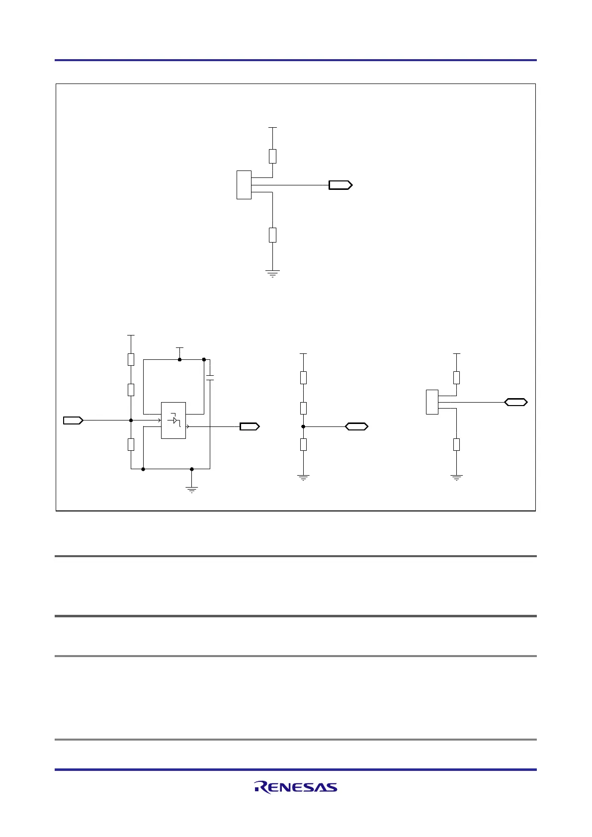
place Silkscreen:
MODE0 Jumper
MODE0
MODE0
10K 1K0
3.3V or 5V
E0VCC
R121
JP38
R120
P5<3>
3
2
1
OUT
3
2
1
FLMD1 Jumper
place Silkscreen:
FLMD2 Jumper
place Silkscreen:
FLMD2FLMD1
FLMD1
FLMD0
place Silkscreen:
FLMD0 Circuit
FLMD2
10K
10K
1K0
1K0
1K010K
SN74LV1T126DCKR
100n
E0VCC
SYSVCC
3.3V or 5V
3.3V or 5V
E0VCC
3.3V or 5V
E0VCC
3.3V or 5V
R19
C83
IC17
R5
R130
JP41
R122
R124
JP40
R123
JP39
P6<14>
FLMD0 P6<13>
FLMD0_TOOL
1
4
5
3
2
21
3
2
1
21
BI
OE
VCC
YGND
A
2
1
IN
OUT
3
2
1
2
1
BI
6.1 Operating mode selection
 Loading...