RH850/U2A 144pin 6. Other Circuitry
R20UT5089ED0101 Rev.1.01 Page 19 of 56
July 08, 2022
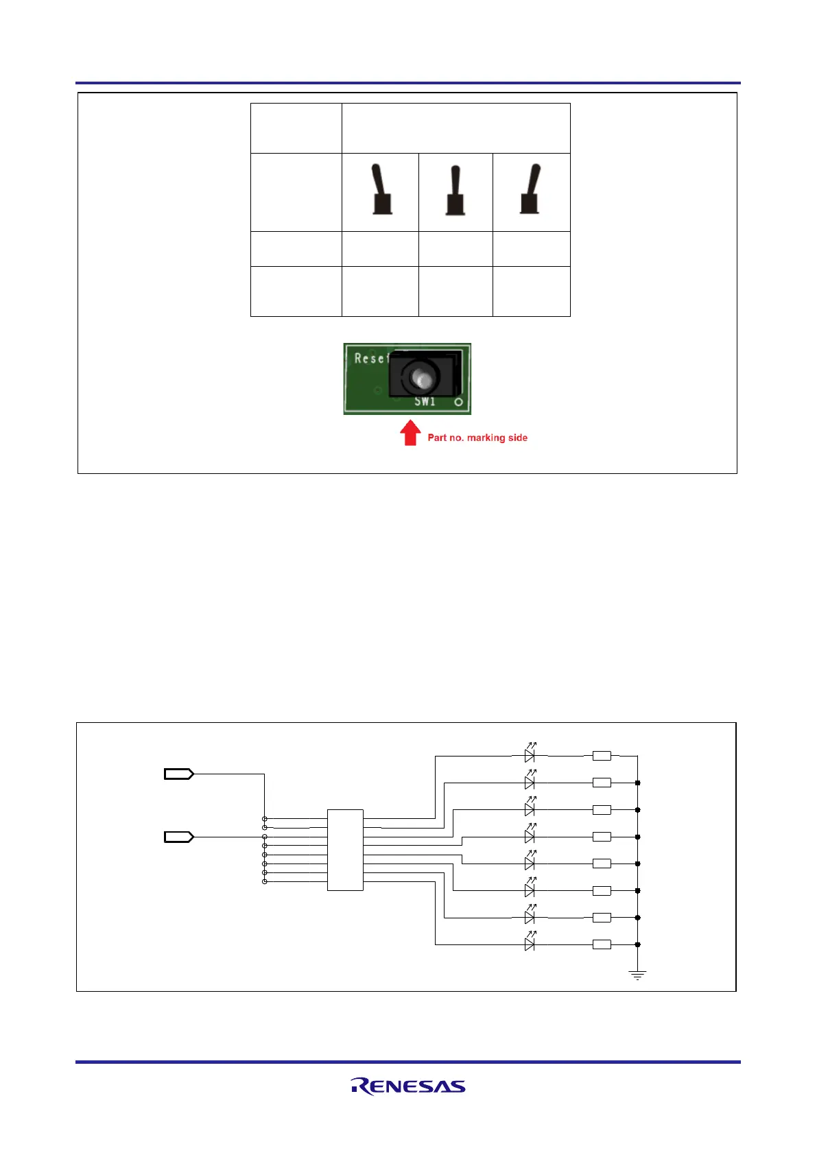
6.3 Signaling LEDs
Eight LEDs are provided to allow visual observation of the output state of device port pins.
Device pins AP2_8, AP2_9 and P4_5 to P4_10 are connected to the odd pins of the pin header
CN7, while the LEDs 2 to 9 are connected to the even CN7 pins.
Thus, the LEDs can be either connected to
• the device pins AP2_8, AP2_9 and P4_5 to P4_10 by closing the connection on CN7 using a jumper, or
• any device pin by connecting directly with the even CN7 pins using a separate cable.
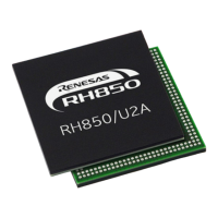
function
Viewed from part no. marking side
terminals
momentary
permanent
permanent
6.3 Operation of RESET switch
Signalling LEDs
1k82
1k82
1k82
1k82
1k82
1k82
1k82
yellow
yellow
yellow
yellow
yellow
yellow
yellow
1k82
8
6
7
8
9
10
header 16way
yellow
9
5
LED9
R33
LED8
R32
LED7
R31
LED6
R30
LED5
R29
LED4
R28
LED3
R27
LED2
R26
CN7
P4<10..5>
LED6
LED7
LED9
LED2
LED4
LED8
LED5
LED3
AP2<15..0>
1615
1413
1211
109
87
65
43
21
IN
IN
51 61
31 41
11 21
9 01
8
6
4
2
7
5
3
1
6.4 Signalling LED circuit
 Loading...