RL78/G13 CHAPTER 12 SERIAL ARRAY UNIT
R01UH0146EJ0100 Rev.1.00 594
Sep 22, 2011
(4) Processing flow (in continuous reception mode)
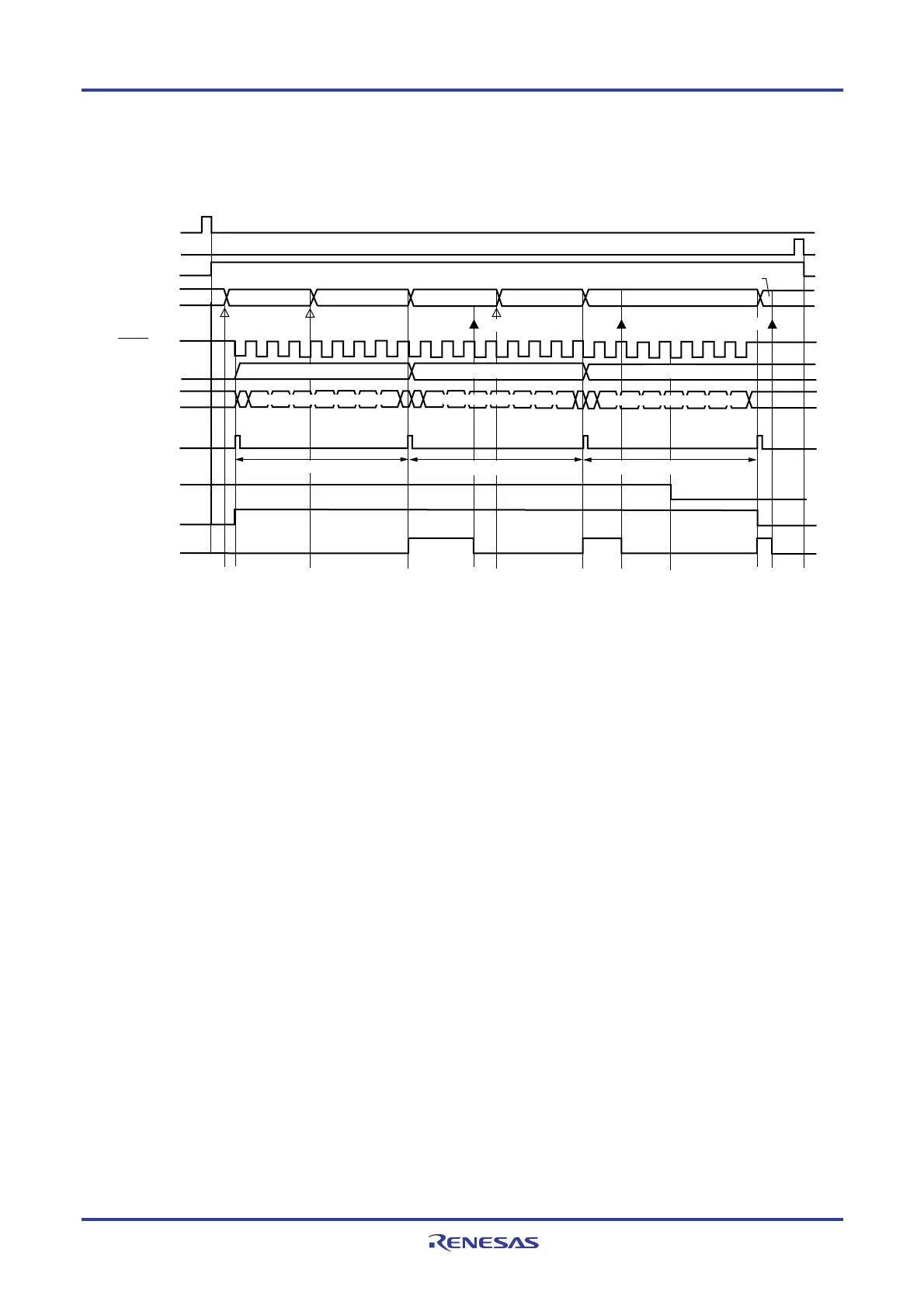
Figure 12-40. Timing Chart of Master Reception (in Continuous Reception Mode) (Type 1: DAPmn = 0, CKPmn = 0)
SSmn
SEmn
SDRmn
SCKp pin
SIp pin
Shift
register mn
INTCSIp
TSFmn
Reception & shift operation
Reception & shift operation
BFFmn
Reception & shift operation
MDmn0
Data reception (8-bit length)
Data reception (8-bit length)
Data reception (8-bit length)
STmn
<4> <5>
Dummy data Dummy data
Receive data 3
Write
Read
Read
Read
Write
<1>
<2>
<3>
<2>
<3>
<4> <2>
<7> <8>
Dummy data
Write
<6>
<3>
Receive data 2
Receive data 1
Receive data 1
Receive data 2
Receive data 3
Caution The MDmn0 bit can be rewritten even during operation.
However, rewrite it before receive of the last bit is started, so that it has been rewritten before the
transfer end interrupt of the last receive data.
Remarks 1. <1> to <8> in the figure correspond to <1> to <8> in Figure 12-41 Flowchart of Master Reception
(in Continuous Reception Mode).
2. m: Unit number (m = 0, 1), n: Channel number (n = 0 to 3), p: CSI number (p = 00, 01, 10, 11, 20, 21,
30, 31), mn = 00 to 03, 10 to 13

 Loading...


