RL78/G13 CHAPTER 18 STANDBY FUNCTION
R01UH0146EJ0100 Rev.1.00 855
Sep 22, 2011
(1) Oscillation stabilization time counter status register (OSTC)
This is the register that indicates the count status of the X1 clock oscillation stabilization time counter.
The X1 clock oscillation stabilization time can be checked in the following case.
• If the X1 clock starts oscillation while the high-speed on-chip oscillator clock or subsystem clock is being used as
the CPU clock.
• If the STOP mode is entered and then released while the high-speed on-chip oscillator clock is being used as
the CPU clock with the X1 clock oscillating.
The OSTC register can be read by a 1-bit or 8-bit memory manipulation instruction.
When reset is released (reset by RESET input, POR, LVD, WDT, and executing an illegal instruction), the STOP
instruction and MSTOP bit (bit 7 of clock operation status control register (CSC)) = 1 clear this register to 00H.
Figure 18-1. Format of Oscillation Stabilization Time Counter Status Register (OSTC)
Address: FFFA2H After reset: 00H R
Symbol 7 6 5 4 3 2 1 0
OSTC MOST
8
MOST
9
MOST
10
MOST
11
MOST
13
MOST
15
MOST
17
MOST
18
Oscillation stabilization time status
MOST
8
MOST
9
MOST
10
MOST
11
MOST
13
MOST
15
MOST
17
MOST
18
fX = 10 MHz fX = 20 MHz
0 0 0 0 0 0 0 0 2
8
/fX max. 25.6
μ
s max. 12.8
μ
s max.
1 0 0 0 0 0 0 0 2
8
/fX min. 25.6
μ
s min. 12.8
μ
s min.
1 1 0 0 0 0 0 0 2
9
/fX min. 51.2
μ
s min. 25.6
μ
s min.
1 1 1 0 0 0 0 0 2
10
/fX min. 102.4
μ
s min. 51.2
μ
s min.
1 1 1 1 0 0 0 0 2
11
/fX min. 204.8
μ
s min. 102.4
μ
s min.
1 1 1 1 1 0 0 0 2
13
/fX min. 819.2
μ
s min. 409.6
μ
s min.
1 1 1 1 1 1 0 0 2
15
/fX min. 3.27 ms min. 1.64 ms min.
1 1 1 1 1 1 1 0 2
17
/fX min. 13.11 ms min. 6.55 ms min.
1 1 1 1 1 1 1 1 2
18
/fX min. 26.21 ms min. 13.11 ms min.
Cautions 1. After the above time has elapsed, the bits are set to 1 in order from the MOST8
bit and remain 1.
2. The oscillation stabilization time counter counts up to the oscillation
stabilization time set by the oscillation stabilization time select register (OSTS).
If the STOP mode is entered and then released while the high-speed on-chip
oscillator clock is being used as the CPU clock, set the oscillation stabilization
time as follows.
• Desired OSTC register oscillation stabilization time ≤ Oscillation
stabilization time set by OSTS register
Note, therefore, that only the status up to the oscillation stabilization time set
by the OSTS register is set to the OSTC register after STOP mode is released.
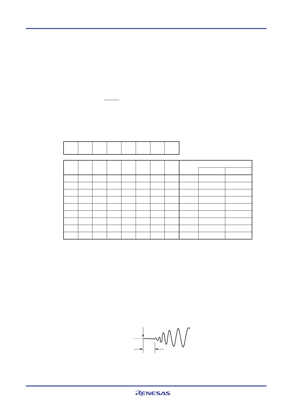
3. The X1 clock oscillation stabilization wait time does not include the time until
clock oscillation starts (“a” below).
STOP mode release
X1 pin voltage
waveform
a
Remark f
X: X1 clock oscillation frequency

 Loading...


