31
www.renishaw.com
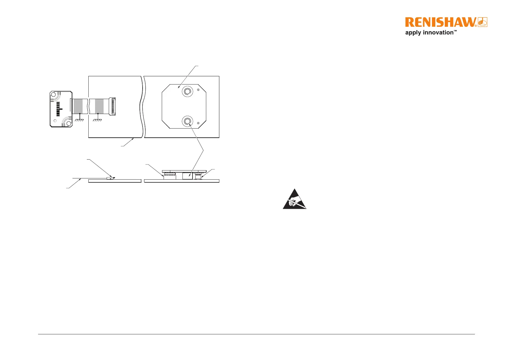
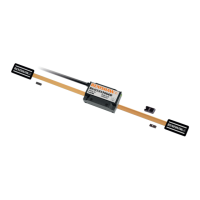
PCB mounting: connecting an FPC variant ATOM readhead
Ensure that the FPC cable being used has the following specications:
FPC input connector
FPC cable
2 mounting holes
M3 through
Output
Customer PCB
Input
ACi interface
Pin 1
Pin 1
Approved ESD precautions must be followed at all times during readhead
and interface electrical connection.
• 16 core
• Conductor pitch 0.5mm
• Minimum exposed conductor strip length 1.5mm
• Maximum exposed conductor strip length 2.5mm (to ensure isolation from the body)
Contact your local Renishaw representative for more information regarding FPC design requirements.
Shielding
For optimum performance:
• Ensure 100% shielding
• Ground the mounting brackets, readhead and FPC cable clamp
• Ensure continuity of all shields
• Maximise the distance between the encoder and motor cables
• Provide appropriate strain relief at the readhead and interface
• The ACi should be contained within a shielded enclosure
Connection
For information on inserting and removing the FPC cable to the mating socket, see page 27.