33
www.renishaw.com
Readhead connection socket
NOTE: Care is required to hold the assembly together as the PCB is xed only to the 15-way connector and the jack screws are loose.
Approved ESD precautions must be followed at all times during readhead andinterface electrical connections.
NOTE: An optional Ri cable guide (A-9693-2577) isavailable to simplify assembly.
Connecting the readhead
For instructions on how to install the Ri cable guide, download the Ri interface cable guide (Renishaw part no. M-9770-9478) from the website at
www.renishaw.com/atomdownloads
Ri interface
1. Open the interface housing by removing the two screws shown (4-40UNC screws and nuts).
2. With the plain side facing up, remove the top half of the housing, so that the interface PCB is exposed and the readhead connection socket isvisible.
3. Taking care not to touch the pins, plugthe connector into the socket in the interface, ensuring correct orientation as shown.
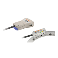
The readhead is connected to the Ri interface via a small, rugged connector to allow for easy feed-through during installation.