58
ATOM linear encoder system
1
All power connections should be used either to minimise voltage drop down the cable or incorporate voltage sensing.
2
Only available on interboard connector.
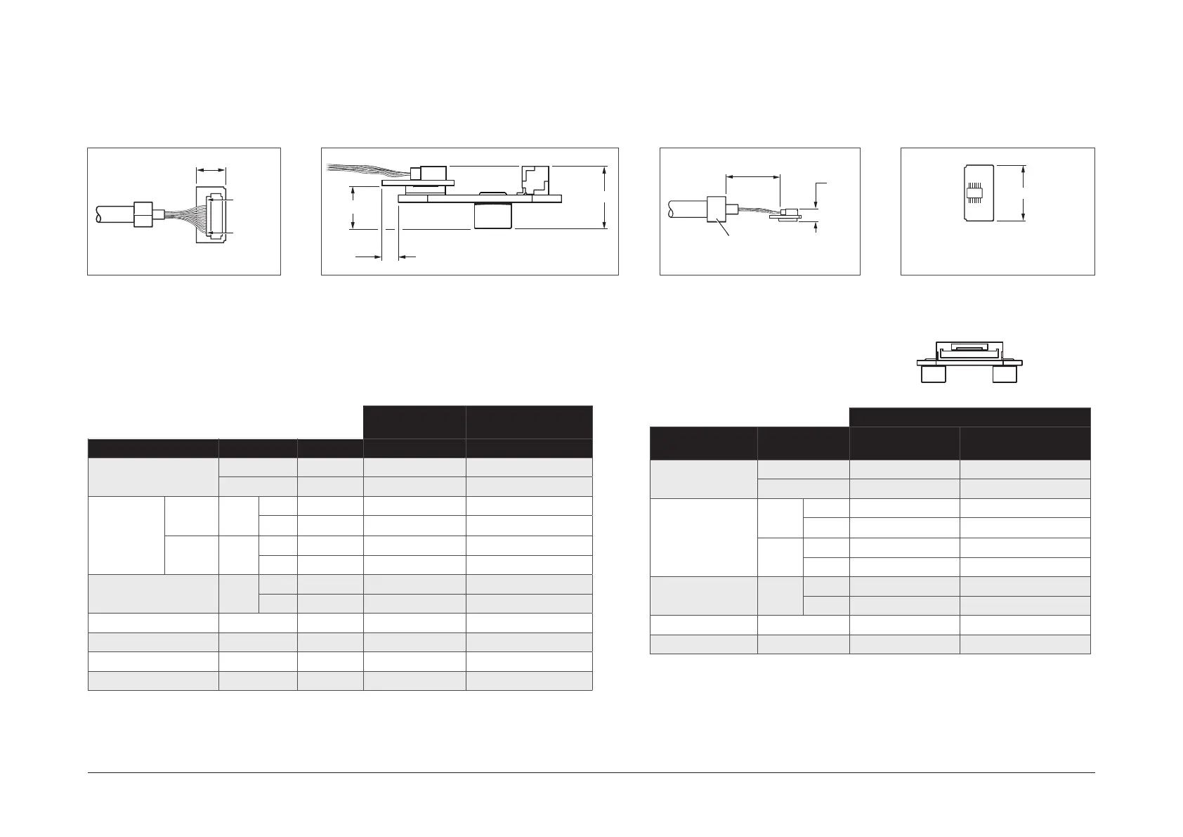
Readhead cable input connector
JST connector
Pin 1
Pin 12
9
1
2
13
14
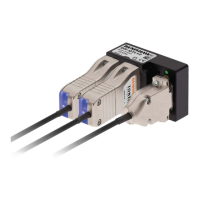
Interboard connector for connection
to Ri, Ti and cabled ACi interfaces
15
Pin 1 Pin 10
ACi JST output connector
4
21 ±1
Cable ferrule nominal
diameter 5.9 ±0.2mm
Output signalsInput signals
JST
2
(on interboard)
Interboard connector
(T)
Function Signal Colour Pin Pin
Power
1
5 V
Brown
11 4
0 V
White
5 13
Incremental Cosine
V
1
+
Red
4 9
−
Blue
3 5
Sine
V
2
+
Yellow
7 12
−
Green
6 14
Reference mark
V
0
+
Violet
10 2
−
Grey
9 8
Set-up V
X
Clear 12 6
Remote CAL CAL
Orange
8 10
Shield - Screen Cable ferrule Cable ferrule
Do not connect - - 1, 2 1, 3, 7, 11
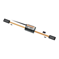
Pin
Function Signal JST connector
A-9412-1001 cable
(15-way D-type)
Power 5 V 9 7, 8
0 V 10 2, 9
Incremental
A
+ 1 14
− 2 6
B
+ 3 13
− 4 5
Reference mark
Z
+ 5 12
− 6 4
Set-up X 7 1
Remote CAL CAL 8 11
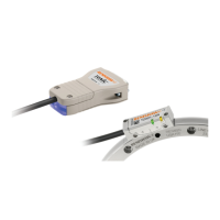
9.5
6.25
2.5