12
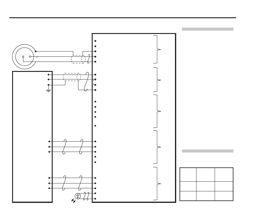
Recommended connection diagram for LP2 with HSI-C interface
NOTES:
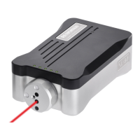
When connecting
the LP2 probe to the
HSI-C interface, use
the connection labelled
STANDARD PROBE.
When the SSR output is
connected as normally
open (NO), the LP2
probe will remain in the
non-triggered (seated)
state if the power
supply is interrupted or
if the probe is damaged.
Probe
status
Normally
open
(NO)
Normally
closed
(NC)
Probe
triggered
Closed Open
Probe
seated
Open Closed
HSI-C interface
SSR probe type and external
LED connector (5-way)
29. Probe type NO
28. Probe type common
27. Probe type NC
26. External LED 10 Vdc
25. External LED 0 Vdc
SSR probe status connector
(5-way)
24. Probe status NO
23. Probe status common
22. Probe status NC
21. Not connected
20. Not connected
Inhibit connector (5-way)
10. Inhibit input
11. Inhibit return
12. 0 Vdc
13. +12 Vdc to +30 Vdc out
(fused at 100 mA)
14. Not connected
Power connector (4-way)
1. +12 Vdc to 30 Vdc supply input
2. 0 Vdc supply
3. 0 Vdc supply
4. Screen
Probe connector (5-way)
19.
18.
17. Screen
16. Standard probe input +
15. Standard probe input −
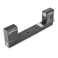
FS1 /FS2 probe holder xed
socket for standard probe
No screen connection
*
*
*
CNC
controller
+12 Vdc to 30 Vdc
0 Vdc
Machine ground
(“star point”)
Connect either
pin24 or pin22,
but do not connect
both pins
Connect either
pin29 or pin27,
but do not connect
both pins
Block 4
Block 1
Block 3
Block 5
Block 6
Probe inhibit function.
Refer to the HSI-C hard-
wired system interface
– congurable installation
guide (Renishaw part
no. H-6527-8501) for
connection information
Outer spring pin, Green
Inner spring pin, Blue
Green/Yellow