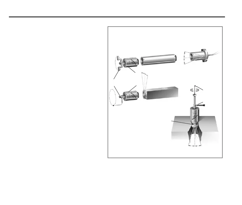
24 Stylus on-centre adjustment with probe holders and sockets
Stylus on-centre adjustment
Stylus position is established using a setting
gauge or dial test indicator.
Lathes – inspection
The stylus is set to the same height as the
spindle centre line to avoid errors when
gauging diameters. The stylus tip position
should correspond to the normal tool tip
position for efcient programming.
1. MA4 90° adaptor
The probe is set through 360°.
2. FS3 adjustable holder
The holder pivots on two Ø6mm balls.
Two opposing screws permit ±4° ne
rotational adjustment.
3. Square holder
Two opposing screws permit ±4° ne
rotational adjustment.
Lathes and machining centres
4. Tool setting
The square tip of the stylus must align
exactly with the machine’s X and Y
axes (machining centres) and X axis
(lathes). Coarse alignment is obtained
by adjusting the stylus tip. The optional
FS1 socket provides ±4° ne rotational
adjustment.
Extension
4°
4°
FS3 holder
Square
holder
LP2
probe
Stylus
4°
4°
4° 4°
FS1
socket
Fine adjustment
Coarse
adjustment