2.2
RTS basics
Getting started
A multicolour LED provides visual indication of selected probe settings and status:
• Trigger filter setting.
• Hibernation setting*.
• Tool setter status – triggered or seated.
• Battery condition.
* in RMI-Q mode only.
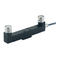
Batteries are inserted or removed as shown (for further information, see page 3.5, “Installing the
batteries”).
On insertion of the batteries, the LED will begin to flash, starting with a LED check (for further
information, see page 4.2, “Reviewing the probe settings”). A LED check displaying a single
flash of red, green, blue indicates that the probe is operating in RMI-Q mode. A LED check displaying
double flashes of red, green, blue indicates that the probe is operating in RMI-QE mode.
System interface
The RTS is optimised for use with the RMI-Q or RMI-QE. The RMI-Q or RMI-QE is a combined
antenna, interface and receiver unit used to communicate between the RTS and the machine
controller. For more details, refer to the RMI-Q radio machine interface installation guide (Renishaw
part no. H-5687-8504) or the RMI-QE radio machine interface installation guide (Renishaw part no.
H-6551-8520).
It is necessary that the RTS is partnered to either an RMI-Q or RMI-QE. Prior to partnering for the first
time, the RTS is pre-set to operate in RMI-QE mode. The LED check will display double flashes of red,
green, blue.
NOTE: The RTS (model RTSQE) is not compatible for use with the older RMI integrated interface/
receiver.
 Loading...