3.2
System
installation
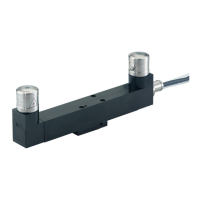
RTS installation guide
Positioning the RTS and RMI-Q or RMI-QE
The probe system should be positioned so that the optimum range can be achieved over the full travel
of the machine’s axes. Always face the front cover of the RMI-Q or RMI-QE in the general direction
of the machining area, ensuring both are within the performance envelope shown in the figure on
page3.
3. To assist in finding the optimum position of the RMI-Q or RMI-QE, the signal quality is
displayed on an RMI-Q or RMI-QE signal LED. Ensure that the signal LED indicates a green or
yellow (good) communication strength when the RTS is operating (see the following note regarding
“Hibernation mode”).
NOTES:
RTS installation with RMI-Q.
RTS has a built-in “hibernation mode” (battery-saving mode) that saves battery life when the
RMI-Q is unpowered or out of range. When an RTS is partnered with an RMI-Q, the RTS goes into
“hibernation mode” 30 seconds after the RMI-Q is unpowered (or the RTS is out of range).
When in “hibernation mode”, the RTS checks for a powered RMI-Q every 30 seconds. If found, the
RTS goes from “hibernation mode” to “stand-by mode”, ready for an M-code. If the RTS goes out
of range (for example, if the RTS is tted to a pallet which is removed from the machine), the system
will automatically re-synchronise within 30 seconds once the RTS is back in range. Allowance must be
made within the machine controller program for this. Hibernation can be changed to 5 seconds or may
be turned off using Trigger Logic™.
“Hibernation mode” does not exist when RTS (model RTSQE) is used with a RMI-QE.
Performance envelope
The RTS and RMI-Q or RMI-QE must be within each other’s performance envelope as shown on
page3.3. The performance envelope shows line-of-sight performance, however, radio transmission
does not require this, providing a reflected path (of less than 15 m (49.2 ft)) is available.
 Loading...