3.6
System
installation
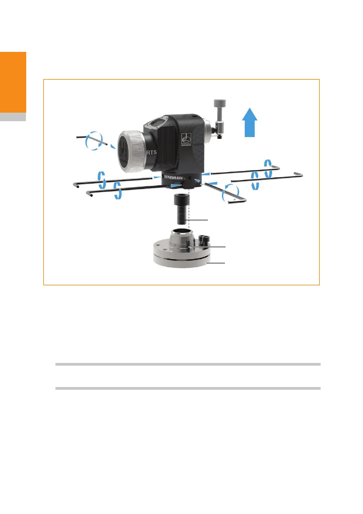
Mounting the probe on a machine table
1. Select a position for the RTS on the machine table. Position to minimise the possibility of collision
and ensure the radio window faces towards the receiver.
2. Separate the base from the body by slackening four screws 1 and two screws 2 using a 2.5 mm
A/F hexagon key.
3. Fit the cap head bolt and T nut (not supplied by Renishaw) and tighten to secure the base to the
machine table.
NOTE: A smaller washer should be tted for a smaller bolt by disassembling and separating the
base plates.
4. Refit the body onto the base and tighten screws 1 and 2. If a square stylus is fitted and fine
rotational adjustment is required, see pages 3.9 – 3.12, “Square stylus setting”, “Coarse
rotational adjustment” and “Fine rotational adjustment” before tightening screws2.
5. Fit the stylus; see page 3.4, “Fitting the stylus, break stem and captive link”, for further
information.
Dowel pins (for more information, see page 2.8, “RTS dimensions”).
Two locating pins (supplied in the tool kit) may be fitted on installations where there is a requirement to
remove and remount the tool setter.
To fit the dowel pins, drill two holes in the machine table to correspond with the two probe base holes.
Place the dowel pins in the holes and refit the probe base.
2.5 mm A/F
0.7Nm – 0.9Nm
(0.52lbf.ft – 0.66 lbf.ft)
× 4
2.5 mm A/F
0.7Nm – 0.9Nm
(0.52lbf.ft – 0.66 lbf.ft)
× 4
Locating pin
Base
M10 / M12 bolt and T nut
(not supplied)
1
1
1
1
2
2
 Loading...