3.2 VANES AND SOFT LIMITS PCB.
Strip
Unscrew and carefully remove both opto switch vanes to give complete
access to the Soft Limits PCB. Do not bend the vanes as this could affect
operation.
Remove 2 off Ty-raps, unsolder probe wires from pins and unplug Hard
Limits PCB cable loom from Soft Limits PCB.
Unscrew 3 off M3 screws to remove Soft Limits PCB.
Rebuild
Insert Soft Limits PCB (A-2116-0570) into hub and secure with 3 off M3
screws (P-SC17-0304).
Solder probe wires to pins. Plug Hard Limits PCB cable loom into socket
on Soft Limits PCB as per figure 3.2a.
Fit new Ty-raps (P-CA66-0922) around probe wires and cable loom to
Soft Limits PCB to give strain relief as shown.
Refit opto switch vanes as per figure 3.2.
Note: For set up of opto switch vanes, consult section 4.2 & 4.3 of
Setting Up.
To continue rebuild go to section 3.1
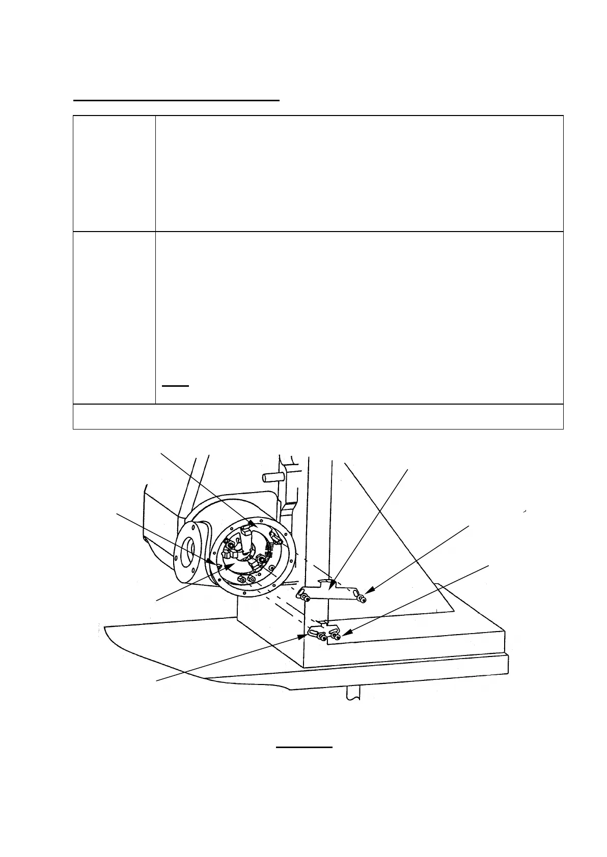
Figure 3.2
6
/Active opto
switch vane
(P-SC17-0304)
(P-SC17-0304)