Rebuild
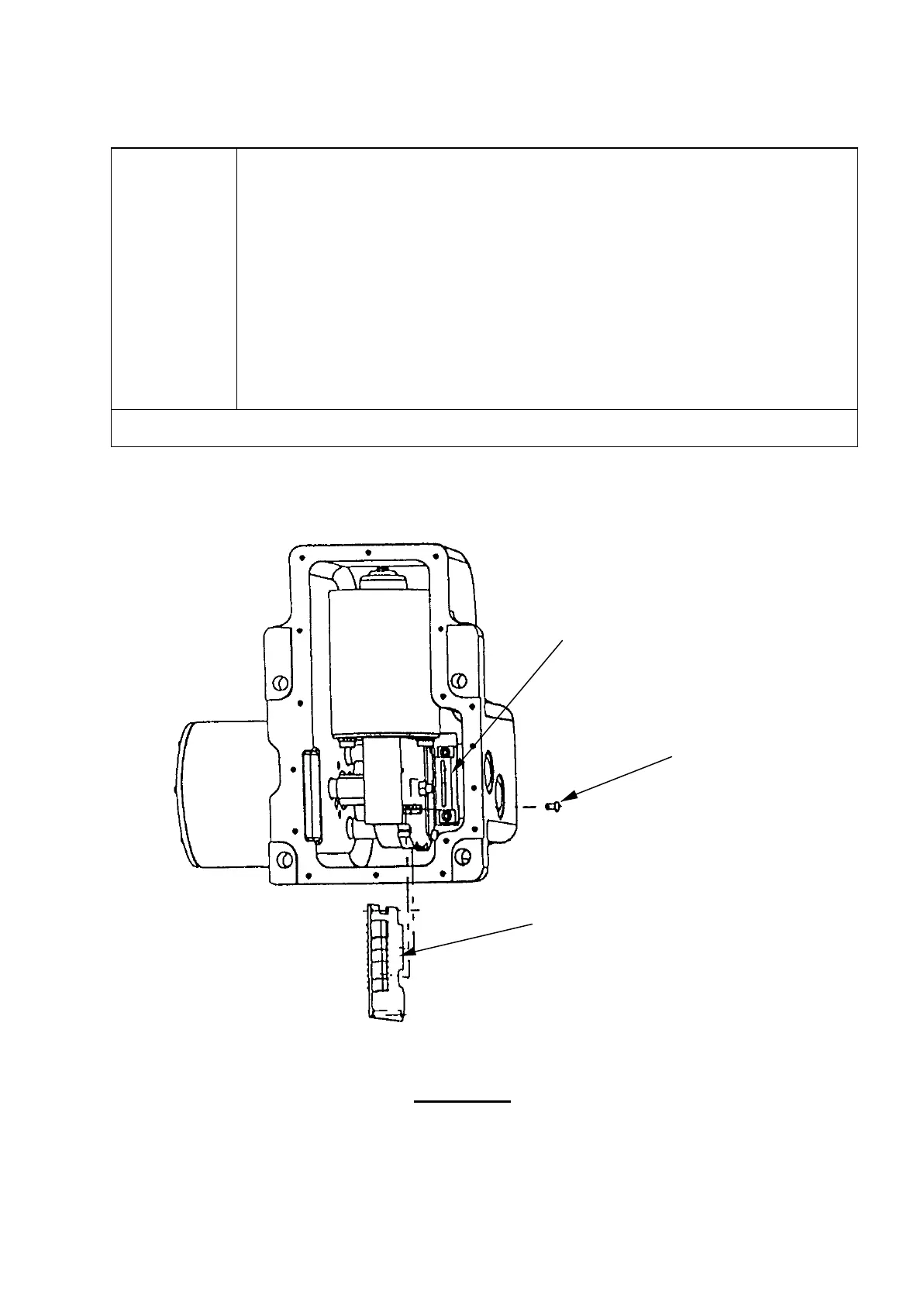
Insert the control PCB (A-2116-0520) into the assembly and push the
board into the connector at the same time as pushing the keyhole slot in
it over the M3 socket screw. Tighten the screw to secure PCB in place
as per figure 3.4a.
Re-connect the main cable wires as per section 4.1 of Setting Up.
Renew cover gasket (M-2116-0084)
Place base cover plate onto casting and secure with 17 off M3 screws
(P-SC02-0308). Torque all screws to 0.7 Nm as per tightening sequence
shown in figure 3.4b.
To continue rebuild go to section 3.1
Figure 3.4a
Motor Connector
(P-SC17-0306)
(A-2116-0520)
10
 Loading...