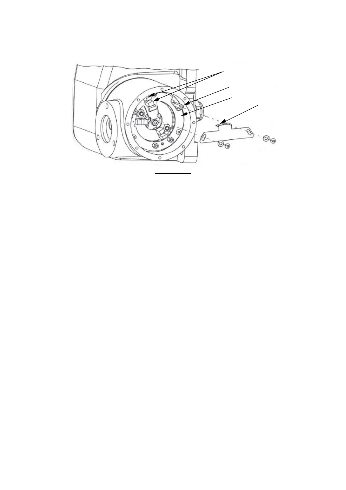
Figure 4.2a
Slide the vane fully anti-clockwise such that the flap lies midway between the poles of
the opto switch.
Drive the hub from ‘Stow’ to ‘Active’ and watch for movement of the pillar relative to
the Soft Limits PCB. Approximately 1mm movement is required.
A lack of movement means that the kinematics will not be preloaded by the
springs and this will result in poor repeatability.
If there is no movement, slide the vane clockwise slightly then drive the hub from
‘Stow’ to ‘Active’ again. If necessary, repeat, making clockwise/anti-clockwise
adjustments until approximately 1mm of relative movement between the pillar and
PCB is observed.
Tighten both screws to 0.7Nm.
Visually check that the springs in the hub wind up approximately 1 mm.
opto switch
flap
pillar
14