17
Assembly of the elongation measuring strips and the extruder holder
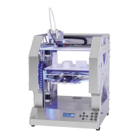
1x extruder holder
2x elongation measuring strips
2x cylinder head screw M5x16
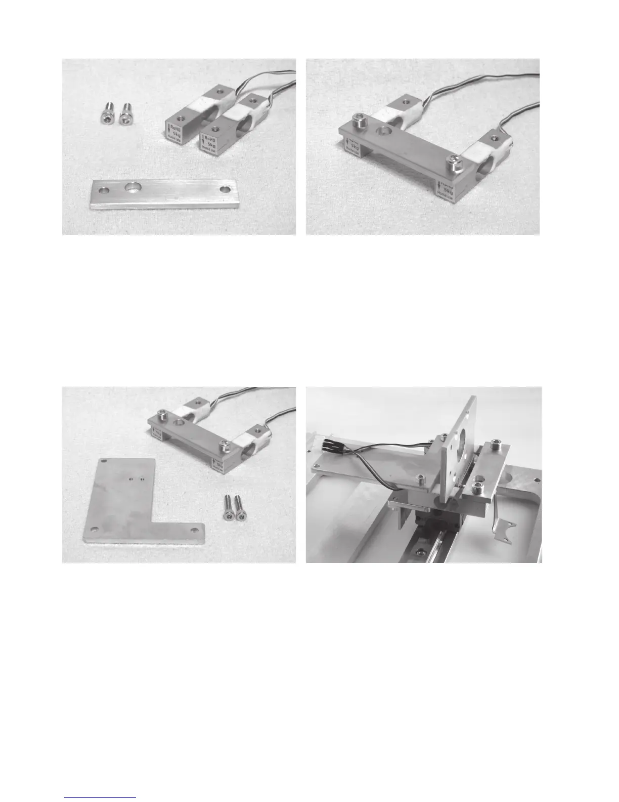
Attach extruder holder to the elongation measuring strips with
the two screws. For this, observe the position of the bores in
the extruder holder (see screen).
Apply screws with threadlocker varnish.
Do not tighten the screws yet though.
The arrows at the head sides of the elongation measuring
strips must point down.
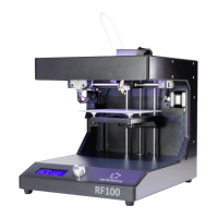
Attach the extruder holder and elongation measuring strips
1x assembly extruder holder with elongation measuring strips
1x holding plate for end stop actuation
2x cylinder head screw M4x20
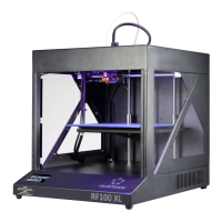
Attach the assembly from the previous construction section
together with the holding plate of the end stop actuation to the
guide carriage as shown.
Apply screws with threadlocker varnish.
Attention, the connection lines of the elongation measuring
strops must be placed above the holding plate (see figure).
Now tighten the two screws of the extruder holder as well.