46
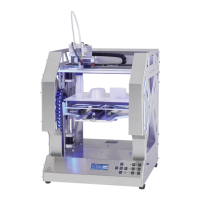
Connect the protective ground (green/yellow line with ring
eyelet) with a cylinder head screw M3x10, a washer and two
sprockets at the top of the undertable.
Caution: This connection creates the safety-technically im-
portant contact between the housing parts and the protec-
tive ground. Always observe the position of the washers and
sprockets:
Screw head > washer > sprocket > ring eyelet > sprocket >
undertable (see image section)
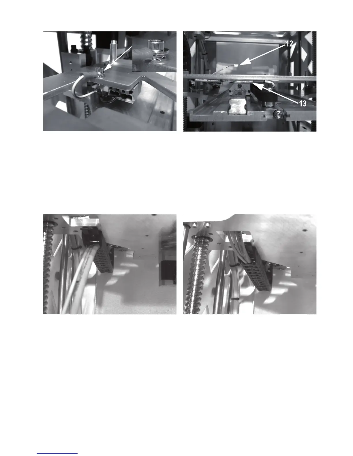
Connect line 13 with the plug connector of the limit switch for
the Y-direction and place the line.
Let line 12 protrude from the drag chain by about 8 cm and at-
tach it to the bore in the undertable with a small cable tie (99
mm). The thermal sensor of the heating plate is attached here
later.
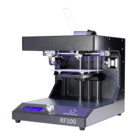
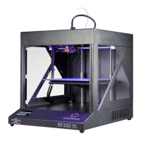
Latch the other end of the drag chain at the end piece of the
Y-plate.
Route the lines of the drag chain upwards through the opening
in the Y-plate.