22
UEZ-IOM (07-23) 1034347-I
INSTALLATION—CONTINUED
Vent Connections—Continued
Vent Terminal Options
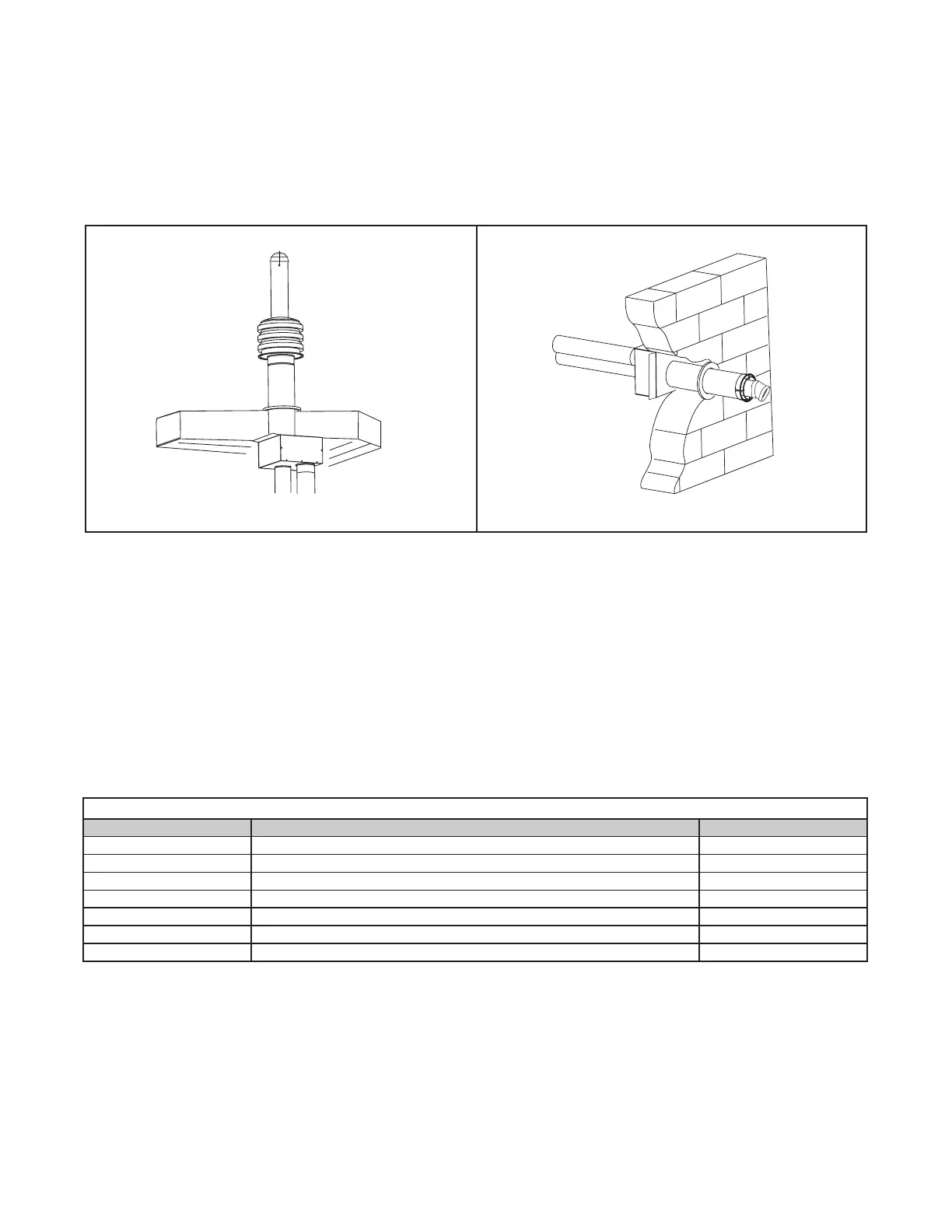
Vent terminal options CC2 (vertical vent configuration) and CC6 (horizontal vent configuration) are shown in Figure 13.
Figure 13. Vent Terminal Options
Vertical Vent Terminal (Option CC2) Installation
• Field-supplied components required for installation of the vertical vent kit are as follows:
a. Vent and combustion air piping: 6- and 8-inch single-wall galvanized pipe
b. Tapered vent pipe diameter reducers and/or increasers, as required
c. Thimble (not required if wall is of non-combustible construction)
d. Flashing
e. Sheet metal screws, tape, and sealant, as required
• Factory-supplied components for installation of the vertical vent kit are listed in Table 15 and shown in Figure 14.
VERTICAL (OPTION CC2)
HORIZONTAL (OPTION CC6)
Table 15. Vertical Vent Terminal/Combustion Air Package (Option CC2) Components
PN Description Quantity
221248 Kit package 1
221069 Concentric adapter box with silicone sealing ring (see Figure 11 and Figure 12) 1
221185 Rain collar (see Figure 14) 1
221250 Combustion air inlet (see Figure 14) 1
221091 Cap, condensate drain connection, 4-inch PVC 1
221215 Bird guard (see Figure 14) 1
37661 Screw, self-drilling, #10-16 × 1/2, bird guard 2

 Loading...


