33
UEZ-IOM (07-23) 1034347-I
Figure 22. Installing Condensate Drain (Unit Sizes 055–110)
Vent Condensate Drain Installation (Unit Sizes 130–310)
NOTE: In Canada, all PVC vent pipe must be approved to ULC S636.
Install the vent condensate drain on unit sizes 130–310 as follows. Ensure that the drain trap is in accordance with
Figure 20.
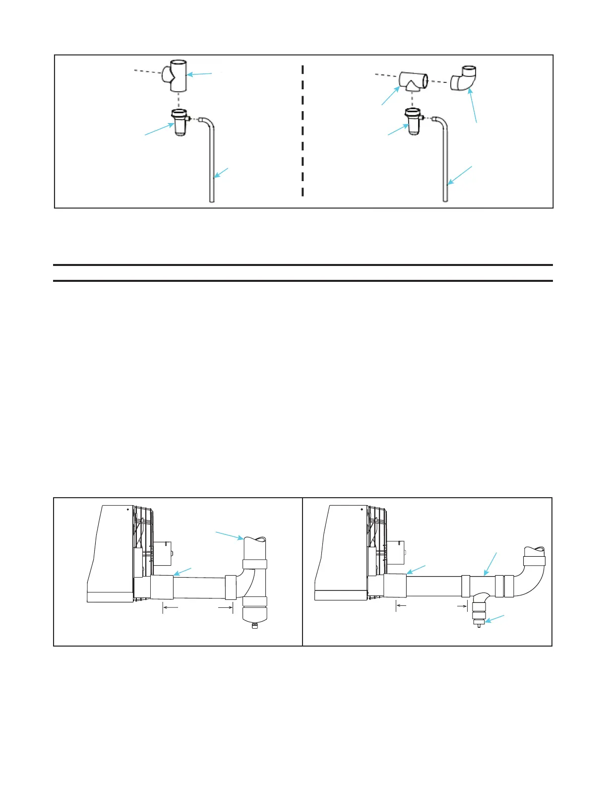
1. For vertical vent (see Figure 23):
a. Connect field-supplied 4-inch coupling to 4-inch vent outlet on back of heater. Ensure that coupling slopes
downward away from heater.
b. Connect 4-inch diameter vent pipe—12-inch (305-mm) minimum length, 24-inch (610-mm) maximum length—to
coupling.
c. For US installations only (see Figure 23, DETAIL A):
(1) Connect field-supplied 4 × 4 × 4 PVC tee to vent pipe.
(2) Connect PVC cap included in option CC2 to tee. Cap is drilled and tapped for 1/2-inch NPT drain connection.
(3) Connect field-supplied condensate drain to cap.
d. For US or Canadian installations (see Figure 23, DETAIL B):
(1) Connect field-supplied PVC tee to vent pipe.
(2) Connect field-supplied fitting(s) to tee as needed for 1/2-inch or larger condensate drain line.
CLEANOUT
CAP
CLEANOUT
CAP
TO VENT
OUTLET ON
BACK OF
HEATER
FIELD-SUPPLIED
DRAIN
FIELD-SUPPLIED
DRAIN
FIELD-SUPPLIED
TEE
FIELD-SUPPLIED
TEE
FIELD-SUPPLIED
TO VENT
OUTLET ON
BACK OF
HEATER
Figure 23. Installing Condensate Drain in Vertical Vent (Unit Sizes 130–310)
COUPLING
DETAIL A (US ONLY)
DETAIL B (US AND CANADA)
DRAIN
FITTING(S)
VENT PIPE
VENT PIPE
TEE
TEE
12–24
(305–610)
12–24
(305–610)
COUPLING
CAP

 Loading...


