7
UEZ-IOM (07-23) 1034347-I
Mounting Height Requirements
⚠ WARNING ⚠
If touched, the vent pipe and internal heater surfaces that are accessible from outside the heater
will cause burns. Suspend the heater a minimum of 5 feet (1.5 meters) above the floor.
In general, a unit should be located 8–12 feet (2.4–3.7 meters) above the floor. At those points where infiltration of
cold air is excessive, such as at entrance doors and shipping doors, it is desirable to locate the unit so that it will
discharge directly toward the source of cold air from a distance of 15–20 feet (4.6– 6.1 meters).
Hazards of Chlorine
The presence of chlorine vapors in the combustion air of gas-fired heating equipment presents a potential corrosion
hazard for separated-combustion heaters with regard to the combustion air inlet. Chlorine is usually found in the form
of freon or degreaser vapors. When chlorine is exposed to flame, it will precipitate from the compound and go into
solution with any condensation that is present in the heat exchanger or associated parts. The result is hydrochloric
acid, which readily attacks all metals including 300 grade stainless steel. Care should be taken to separate these
vapors from the combustion process. This may be done by wise location of the unit vent and combustion air terminals
with regard to exhausters or prevailing wind directions. Chlorine is heavier than air. Keep these facts in mind when
determining installation location of the heater in relation to building exhaust systems.
Clearances
Units must be located so that the clearances listed in Table 3 are provided for with regards to combustion air space,
inspection, and service and for proper spacing from combustible construction. Clearance to combustibles is defined
as the minimum distance from the heater to a surface or object for which it is necessary to ensure that a surface
temperature of 90°F (50°C) above the surrounding ambient temperature is not exceeded. Refer to the Dimensions
section when determining clearances to combustibles.
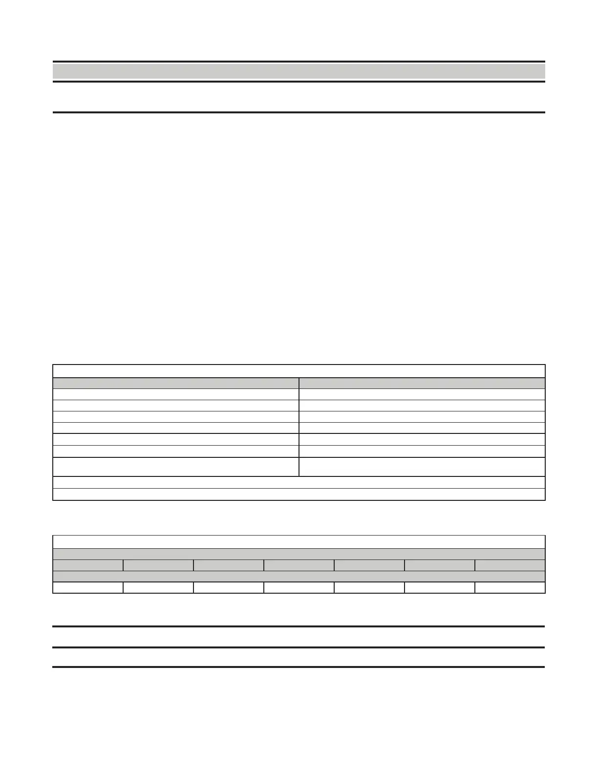
Table 3. Clearances
HeaterSurface Minimum Clearance (Inches (mm))
Top 4 (102)
Flue connector 6 (152)
Access panel 18 (457)
Non-access side 2 (51)
Bottom*
1 (25)
Rear**
18 (457)
Front
Refer to values for variable X (distance from heater to start of floor
coverage) in Heater Throw section
*Suspend the heater so that the bottom is a minimum of 5 feet (1.5 meters) above the floor.
**Measure rear clearance from the fan motor.
Weights
Table 4. Weights
Unit Size
055 085 110 130 180 260 310
Pounds (kg)
85 (39) 103 (47) 123 (56) 230 (104) 245 (111) 360 (163) 395 (179)
Condensate Drain Requirements
⚠ CAUTION ⚠
DO NOT use copper or copper-based alloys for condensate drains.
The combustion process forms condensation, which is collected and directed to a drainage point inside the unit. The
heater is equipped with a 1/2-inch (12.7-mm) PVC pipe for connecting to a condensate drain. The water condensed
from the products of combustion will be acidic. The level of concentration is dependent upon the environment where
the appliance is installed and may be as high as 6 pH.

 Loading...


