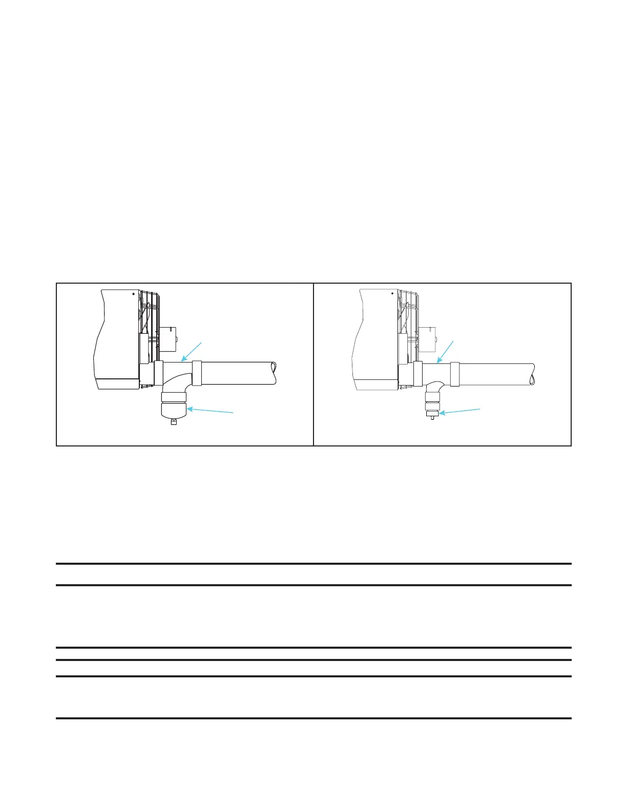
Figure 24. Installing Condensate Drain in Vertical or Horizontal Vent (Unit Sizes 130–310)
Heat Exchanger Condensate Drain Installation
Install the heat exchanger condensate drain in accordance with all piping requirements listed in this manual and
with Figure 21. For drain kit components and installation instructions for replacement heat exchangers, refer to the
replacement parts manual listed in Table 1.
Electrical Connections
⚠ CAUTION ⚠
• Route wires so that they do not contact the flue wrapper or venter housing.
• If any of the original wire supplied with the appliance must be replaced, it must be replaced
with wiring material having a temperature rating of at least 105°C, except for limit control, flame
rollout, and sensor lead wires which must be rated at 150°C.
NOTES:
• Ensure that all wiring is in accordance with the wiring diagram provided with the unit.
• A two-stage valve circuit is NOT available on all models.
34
UEZ-IOM (07-23) 1034347-I
DETAIL A (US ONLY)
DETAIL B (US AND CANADA)
DRAIN
FITTING(S)
TEE
TEE
CAP
INSTALLATION—CONTINUED
Condensate Drain Installation—Continued
Vent Condensate Drain Installation (Unit Sizes 130–310)—Continued
2. For horizontal or vertical vent (see Figure 24):
a. For US installations only (see Figure 24, DETAIL A):
(1) Connect field-supplied 4 × 4 × 4 PVC tee to 4-inch vent outlet on back of heater.
(2) Connect PVC cap included in option CC2 or CC6 to tee. Cap is drilled and tapped for 1/2-inch NPT drain
connection.
(3) Connect field-supplied condensate drain to cap. Balance of vent may be either horizontal or vertical. Ensure
that horizontal vent slopes downward toward drain.
b. For US or Canadian installations (see Figure 24, DETAIL B):
(1) Connect field-supplied PVC tee to 4-inch vent outlet on back of heater.
(2) Connect field-supplied fitting(s) to tee as needed for 1/2-inch or larger condensate drain line. Balance of
vent may be either horizontal or vertical. Ensure that horizontal vent slopes downward toward drain.

 Loading...


