35
UBXC-UDXC-IOM (01-24) 1042980-0
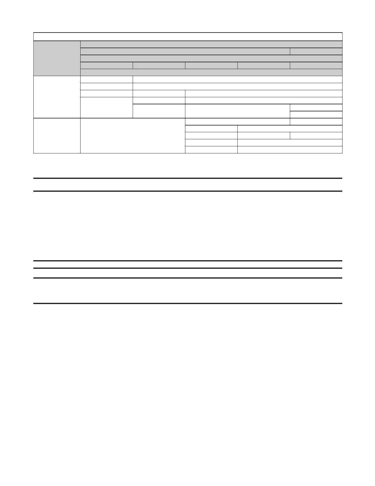
Table 17. Category I Vent Pipe Diameters and Lengths
Connector
Vent Pipe Diameter (Inches (mm))
4 (102) 5 (127)
Unit Size (MBTUh)
30 45 60 75 100
H × L (See Figure 16) Dimension (Feet (Meters))
Double-Wall
6 (1.8) × 4 (1.2) 6 (1.8) × 6 (1.8)
10 (3.0) × 2 (0.6) 8 (2.4) × 8 (2.4)
15 (4.6) × 5 (1.5) 10 (3.0) × 5 (1.5) 10 (3.0) × 10 (3.0)
20 (6.1) × 5 (1.5)
15 (4.6) × 5 (1.5) 15 (4.6) × 15 (4.6)
20 (6.1) × 5 (1.5) 20 (6.1) × 20 (6.1)
20 (6.1) × 20 (6.1)
30 (9.1) × 30 (9.1)
Single-Wall —
6 (1.8) × 2 (0.6) 6 (1.8) × 4 (1.2)
8 (2.4) × 2 (0.6) 8 (2.4) × 4 (1.2)
10 (3.0) × 2 (0.6) 10 (3.0) × 4 (1.2) 10 (3.0) × 5 (1.5)
15 (4.6) × 2 (0.6) 15 (4.6) × 5 (1.5)
20 (6.1) × 2 (0.6) 20 (6.1) × 5 (1.5)
Electrical Connections
⚠ CAUTION ⚠
• All electrical wiring and connections, including electrical grounding MUST be made in accordance
with the National Electric Code (ANSI/NFPA No. 70, latest edition) or, in Canada, the Canadian
Electric Code (Part 1, CSA C.22.1). In addition, the installer should be aware of any local ordinances
or gas company requirements that might apply.
• Route wires so that they do not contact the flue wrapper or venter housing.
• If any of the original wire supplied with the appliance must be replaced, it must be replaced with
wiring material having a temperature rating of at least 220°F (105°C), except for limit control,
flame rollout, and sensor lead wires which must be rated at 302°F (150°C).
NOTES:
• Ensure that all wiring is in accordance with the wiring diagram provided with the unit.
• A two-stage valve circuit is NOT available on all models.
• If the installation requires a stepdown transformer, follow the instructions shipped with the option package for
installing the transformer.
• All units have a built-in disconnect switch (see Figure 17).