37
UBXC-UDXC-IOM (01-24) 1042980-0
Control Connections
• Make thermostat connections at the terminal strip on the back of the heater (see Figure 17). The strip has five
terminals: C, R, G, W1, and W2. Refer to the wiring diagram provided with the heater. Wires from the terminal
strip are factory-wired to the circuit board. Ensure that if there is a heat anticipator setting on the thermostat, it is
set at 0.6 amps or in accordance with the amperage value noted on the heater wiring diagram.
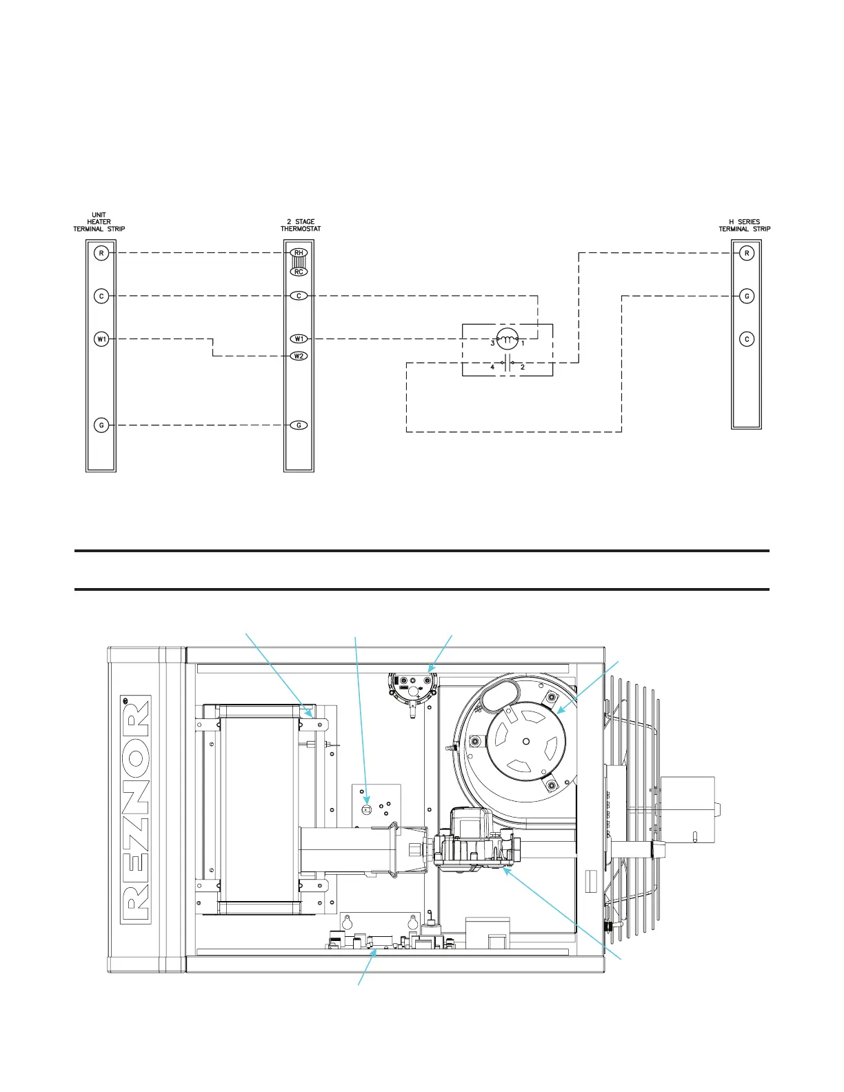
• If the installation features a heater and an H series Huracan
TM
destratification fan controlled by a single two-stage
thermostat, ensure that the wiring is in accordance with the wiring diagram shown in Figure 19.
Figure 19. Heater and Destratification Fan Wiring Diagram
CONTROLS
NOTE: Refer to the TROUBLESHOOTING section for probable causes and reset instructions for
the following controls.
Figure 20. Control Locations (Typical)
SWITCH
LIMIT SWITCH
PRESSURE SWITCH
VENTER WHEEL AN
MOTOR ASSEMBLY
FAN
MOTOR
COMBINATION
GAS VALVE