38
UBXC-UDXC-IOM (01-24) 1042980-0
CONTROLS—CONTINUED
Pressure Switch
⚠ DANGER ⚠
Safe operation of this unit requires proper venting flow. NEVER bypass the pressure switch or
attempt to operate the unit without the venter running and the proper flow in the vent system.
Hazardous conditions could result.
• The pressure (combustion air proving) switch (see Figure 20) is a pressure-sensitive switch that monitors air
pressure to ensure that proper combustion airflow is available.
• On standard units, the pressure switch is a single-pole/normally-open device that closes when a negative pressure
(refer to Table 18) is sensed in the venter housing. On separated-combustion units, the pressure switch senses
the differential pressure (refer to the separated-combustion conversion instructions provided with the conversion
kit) between the negative pressure in the venter housing and the pressure in the cabinet.
• At startup when the heater is cold, the sensing pressure is at the most negative level, and as the heater and flue
system warm up, the sensing pressure becomes less negative. After the system has reached equilibrium (about
20 minutes), the sensing pressure levels off.
• If a restriction or excessive flue length/turns cause the sensing pressure to be outside the pressure switch setpoint,
the switch will function to shut off the main burner. The main burner will remain off until the system has cooled
and/or the flue system resistance is reduced.
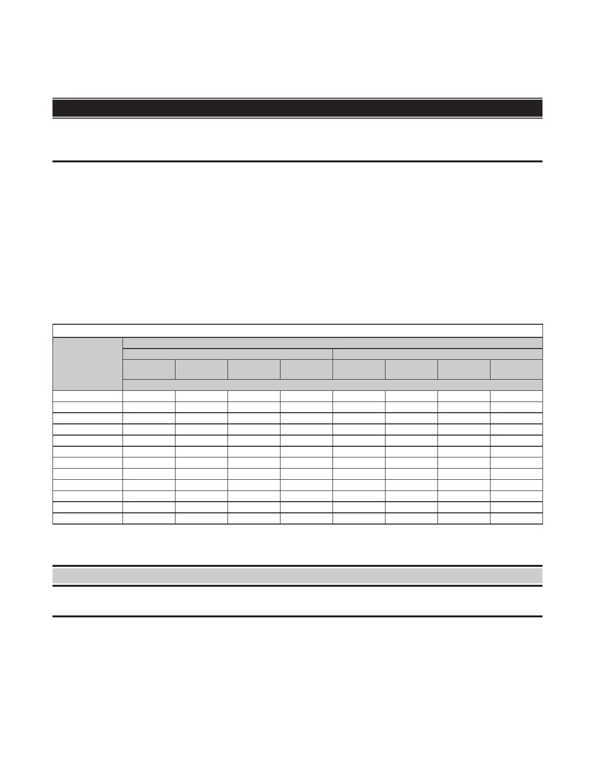
Table 18. Pressure Switch Settings For Standard Units
Unit Size
(MBTUh)
Model
UBXC UDXC
Startup
Cold
Equilibrium
Hot
Setpoint
OFF
Setpoint
ON
Startup
Cold
Equilibrium
Hot
Setpoint
OFF
Setpoint
ON
Negative Pressure (IN WC)
30 1.20 0.90 0.50 0.70 1.20 0.90 0.65 0.80
45 1.00 0.80 0.45 0.65 1.00 0.80 0.50 0.65
60 0.90 0.80 0.60 0.80 0.90 0.80 0.40 0.55
75 0.80 0.70 0.50 0.70 0.80 0.70 0.45 0.60
100 0.90 0.70 0.45 0.65 0.90 0.70 0.50 0.65
125 1.40 1.00 0.60 0.80 1.40 1.00 0.80 0.95
150 0.70 0.60 0.40 0.60 0.70 0.60 0.35 0.50
175 2.30 1.40 1.10 1.30 0.80 0.70 0.40 0.55
200, 225 2.30 1.60 1.10 1.30 2.30 1.60 1.10 1.30
250 2.70 1.80 1.30 1.50 2.70 1.80 1.10 1.30
300 2.50 1.90 1.30 1.50 2.50 1.90 1.10 1.30
350, 400 2.10 1.60 1.30 1.50 2.10 1.60 1.30 1.50
High Temperature Limit Switch
⚠ WARNING ⚠
The automatic-reset high temperature limit switch will continue to shut down the heater until the
cause is corrected. Never bypass this switch as hazardous conditions could result.
All units are equipped with a temperature-activated, automatic-reset high temperature limit switch (see Figure 20).
The switch is factory-set and is non-adjustable. If the setpoint is reached, the switch interrupts the electric supply to
the combination gas valve. This safety device provides protection in the case of motor failure or lack of airflow due
to a restriction at the inlet or outlet.
Venter Wheel and Motor Assembly
The venter motor is assembled to the venter wheel (see Figure 20) and operates to provide combustion airflow.
Operation is controlled by the circuit board (refer to Circuit Board (DSI Control Module) section).