6
UBXC-UDXC-IOM (01-24) 1042980-0
GENERAL INFORMATION—CONTINUED
Heater Location
⚠ CAUTION ⚠
• Unit heaters should not be used in an application where the heated space temperature is below
40°F (4°C). Operating under low ambient conditions may cause condensation to form in the heat
exchanger.
• Do not locate the heater where it may be exposed to water spray, rain, or dripping water.
For best results, the heater should be mounted with certain rules in mind:
• Units should always be arranged to blow toward or along exposed wall surfaces, if possible. Where two or more
units are installed in the same room, a general scheme of air circulation should be maintained for best results.
• Suspended heaters are most effective when located as close to the working zone as possible, and this fact should
be kept in mind when determining the mounting heights to be used. However, care should be exercised to avoid
directing the discharged air directly on the room occupants.
• Partitions, columns, counters, or other obstructions should be taken into consideration when locating the unit heater
so that a minimum quantity of airflow will be deflected by such obstacles.
• When units are located in the center of the space to be heated, the air should be discharged toward the exposed
walls. In large areas, units should be located to discharge air along exposed walls with extra units provided to
discharge air in toward the center of the area.
Clearances
Units must be installed so that the clearances listed in Table 1 are provided for with regards to combustion air space,
inspection, and service and for proper spacing from combustible construction. Clearance to combustibles is defined
as the minimum distance from the heater to a surface or object for which it is necessary to ensure that a surface
temperature of 90°F (50°C) above the surrounding ambient temperature is not exceeded.
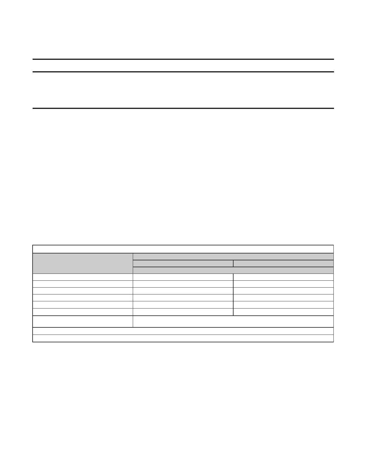
Table 1. Clearances
Heater
Surface
Unit Size (MBTUh)
30–125 150–400
Minimum Clearance (Inches (mm))
Top 1 (25) 4 (102)
Flue connector 6 (152) 6 (152)
Access panel 18 (457) 18 (457)
Non-access side 1 (25) 2 (51)
Bottom*
1 (25) 1 (25)
Rear**
18 (457) 18 (457)
Front
Refer to values for variable X (distance from heater to start of floor coverage)
in Heater Throw Distances with Standard Horizontal Louvers section
*Suspend the heater so that the bottom is a minimum of 5 feet (1.5 meters) above the floor.
**Measure rear clearance from the fan motor.
Heater Throw Distances with Standard Horizontal Louvers
Figure 1 shows throw patterns and Table 2 and Table 3 list throw distances for heaters suspended at varying
mounting heights. The louver angles listed are relative to the top of the heater. The throw pattern changes with the
addition of optional vertical louvers and/or downturn nozzles.