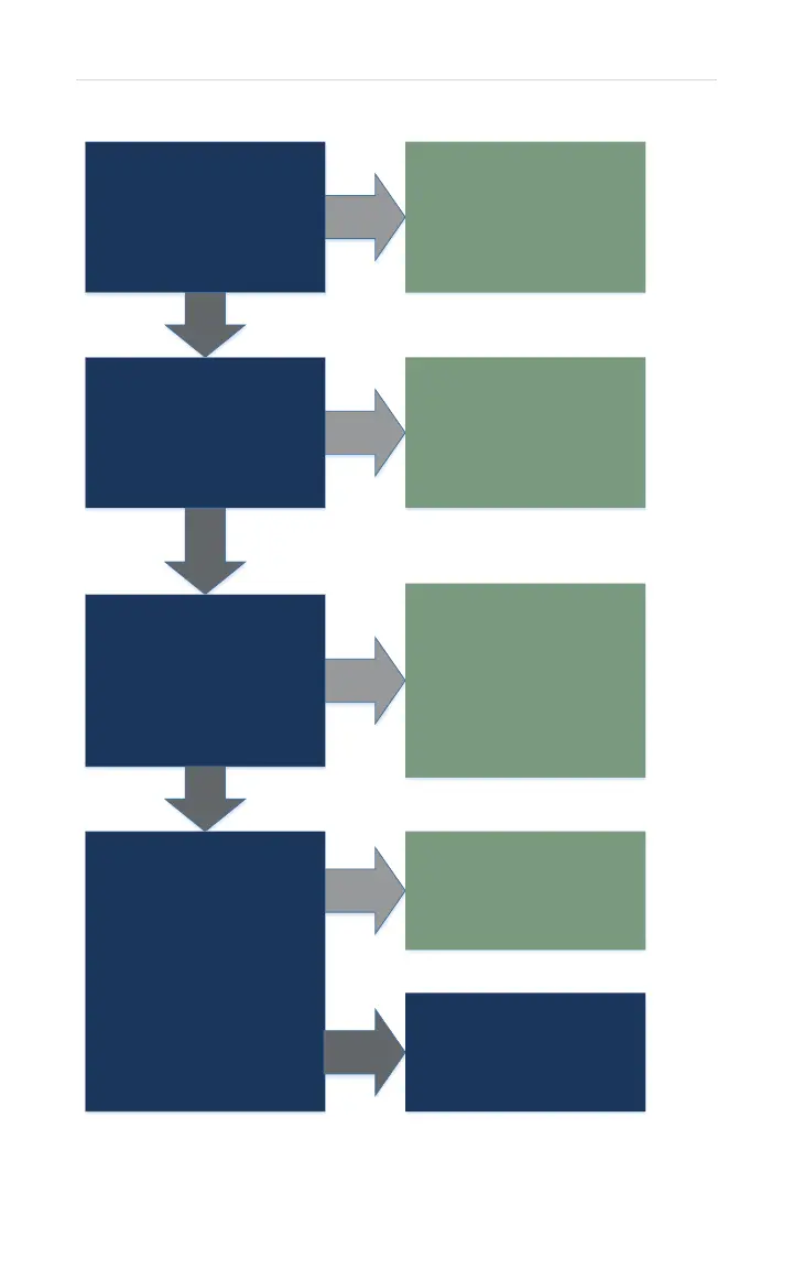
While attempting to ignite
test DC volts across #1 wire
(Red) & #2 wire (Black) on
connector R:
1.5 – 14 DC Volts
YES
Remove & reinsert R.
Operate unit again.
IF Code 11 appears:
Replace control board.
NO
Turn power OFF. Remove
connector R& measure
resistance across same
wires:
40 – 80 OHMS
YES
Remove & reinsert PGFR
connectors. Retest R.
IF resistance test fails:
Replace gas control valve.
NO
Turn power OFF.
Remove connector K.
On connector K: Using the
BLACK WIRE as the
common – individually check
resistance for Yellow, White,
Grey, Red, & Blue wires:
0.8K – 2.4K OHMS
YES
Make sure all wires are
connected to Gas Control
Valve. Retest connector K.
IF test fails: Replace gas
control valve.
NOTE: IF Grey wire failed
ohms test, replace manifold
assembly.
NO
Gas control valve is OK.
Reconnect connector K.
Turn power ON.
While unit is attempting to
ignite - On connector K:
Using the BLACK WIRE as
the common – Individually
check DC volts for Yellow,
White, Grey, Red, & Blue
wires:
90 – 120 DC Volts
Remove & reinsert K.
Operate unit again. IF 11-
Error Code appears:
Replace control board.
NO
Control board is OK.
IF ALL components tested
OK: CHECK GAS SUPPLY,
VENTING, & GROUND.
YES