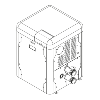
19
SHUTOFF
VALVE
UNION
F10817
Figure 14. Manual Shuto Valve Installation
Gas Pressure Adjustment Locations
CAP
CLOCKWISE TO INCREASE
GAS VALVE
SUPPLY PRESSURE
TAP ON INLET SIDE
GAS FLOW
MANIFOLD
PRESSURE TAP
Figure 15. Gas Valve Adjustment
Pipe Sizing for Gas Connection
The capacities shown below are based on using SCH
40 black iron pipe. For capacities using other materials,
consult local codes.
Maximum Equivalent Pipe Length
ft (m)
Natural Gas 1000 BTU/FT³ 0.60 Specic Gravity @ 0.5 in.
WC Pressure Drop
Propane Gas 2500 BTU/FT³ 1.53 Specic Gravity @ 0.5 in
WC Pressure Drop
Model
No.
Size 3/4" Size 1" Size 1-1/4" Size 1-1/2"
NAT PRO NAT PRO NAT PRO NAT PRO
264
15
(4.6)
35
(10.7)
50
(12.2)
125
(38.1)
210
(64.0)
480
(146.3)
445
(135.6)
404 *
15
(4.6)
20
(8.8)
55
(16.8)
95
(29.0)
225
(68.6)
215
(65.5)
280
(85.3)
* A 3/4" gas line can be used for up to 5' (1.5 m) maximum length from
the gas valve in addition to the sediment trap.
Table L. Gas Pipe Sizing
Gas Regulator Best Practices
From the gas pressure regulator, it is recommended to
have no less than 10 pipe diameters of straight smooth
pipe downstream of the regulator discharge and to have
no less than 10 linear feet (not including ttings) between
the regulator and the inlet to the appliance for proper
operation.
Flow Rates
Model
Pipe Size
in. (mm)
Min. GPM (lpm) Max. GPM (lpm)
264/404 2 (50.8) 40 (151) 100 (379)
* When flow rates exceed maximum GPM an external auxiliary bypass
valve is required. See External Bypass Valve Section on page 21
for details.
Table M. Min/Max Flow Rates
F10818
Figure 16. Water Flow
Flow
GPM (lpm)
Pressure Drop
Ft. of Head (m of Head)
264 404
40 (151) 7.2 (2.2) 13.4 (4.1)
50 (189) 10.0 (3.1) 16.5 (5.0)
60 (227) 12.6 (3.8) 19.5 (5.9)
70 (265) 17.0 (5.2) 23.7 (7.2)
80 (303) 24.0 (7.3) 28.3 (8.6)
90 (341) 30.3 (9.2) 33.2 (10.1)
100 (379) 36.0 (10.9) 37.0 (11.3)
Table N. Heat Exchanger Pressure Drops
NOTE: Table capacity is based on 2" Schedule 40 piping.
 Loading...