39
5 ft. (1.52 m) MAX
POOL OR SPA
MAX
MAY REQUIRE ADJUSTMENT
FOR HIGHER PRESSURE
FOR LOWER PRESSURE
Figure 60. Pressure Switch Adjustment Requirements
NOTE:
If heater is installed outside of the limits shown,
a higher-pressure rated (11 psi / 76 kPa) switch may be
used. A ow switch, mounted and wired adjacent to the
heater, may be used in place of the factory-mounted
pressure switch. See "Illustrated Parts List" on page
84 for 11 psi / 76 kPa water pressure switch.
Two-Speed and Variable Speed Pumps
In some cases, the ow on the low-speed is insucient
to operate the heater. This is apparent when the water
pressure switch cannot be further adjusted or if the heater
makes banging noises or shuts o on high limit. In these
cases, the pump must be run at high speed when heating
the water.
A
CAUTION: Do not operate the heater without the
function of a properly-adjusted water pressure switch or
ow switch.
Cabinet Limit Switch
Heaters are equipped with a cabinet limit switch to prevent
the overheating of the components inside the cabinet in
case of any ue gas leakage from combustion chamber. It
is a "manual-reset" type switch that must be reset by the
service technician after making sure any leaks or damage
to the unit has been xed.
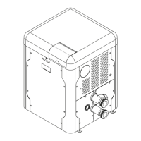
Figure 61. Cabinet Limit Switch – Manual-Reset
High Limits
The heater is equipped with two high limits, both are
automatic and are located in the inlet/outlet header.
Although both limits are preset to auto-reset, the control
board will request the operator to press "MODE" key if
either limit is tripped while the heater is running.
NOTE: An erratic high limit is often characteristic of an
internal heat exchanger problem, e.g. scale build-up, or
defective bypass. Refer to "Troubleshooting" on page
48.
AUTO-RESET
F10848
Figure 62. High Limit Switch
High Limit Removal
1. Shut off main electrical power switch to heater.
2. Remove inlet/outlet sheet metal access panel.
3. Remove defective high limit and replace with the
correct, new high limit.
4. Replace access panel.
Adjusting Valve Manifold Pressure
1. Remove the cap to gain access to the adjustment
screw.
2. Turn the adjustment screw clockwise to increase
pressure. (For example, at -0.6" WC turning
clockwise will increase the pressure to -0.5" WC,
-0.4" WC, etc.)
3. The manifold pressure should be negative -0.30
"WC (+/- 0.20 "WC) while running. If a combustion
analyzer is available, the O2 reading should be
between 4.5 - 5.5% O2 while running.
4. Install the cap before reading the manifold pressure.
GAS VALVE
MANIFOLD
PRESSURE TAP
Figure 63. Manifold Pressure Adjustment
 Loading...