8
U.S. Installations
1
Canadian Installations
2
A
Clearance above grade, veranda, porch, deck, or
balcony
1' (30 cm) 1' (30 cm)
B Clearance to window or door that may be opened
4' (1.2 m) below or to side of
opening
3' (91 cm)
C Clearance to permanently closed window
* *
D
Vertical clearance to ventilated sot located above the
terminal within a horizontal distance of 2' (61 cm) from
the centerline of the terminal
5' (1.5 m)
*
E Clearance to unventilated sot
* *
F Clearance to outside corner
* *
G Clearance to inside corner 6' (1.83 m)
*
H
Clearance to each side of center line extended above
meter/regulator assembly
*
3' (91 cm) within a height
15' (4.5 m) above the meter/
regulator assembly
I Clearance to service regulator vent outlet
*
6' (1.83 m)
J
Clearance to non-mechanical air supply inlet to
building or the combustion air inlet to any other
appliance
4' (1.2 m) below or to side of
opening; 1' (30 cm) above
opening
3' (91 cm)
K Clearance to mechanical air supply inlet
3' (91 cm) above if within
10' (3 m) horizontally
6' (1.83 m)
L
Do not terminate above paved sidewalk or paved
driveway
Slip hazard due to frozen
condensate
Slip hazard due to frozen
condensate
M Clearance under veranda, porch, deck or balcony
*
1' (30 cm)
t
1
In accordance with the current ANSI Z223.1/NFPA 54 National Fuel Gas Code.
2
In accordance with the current CAN/CSA-B149 Installation Codes.
t
Permitted only if veranda, porch, deck, or balcony is fully open on a minimum of two sides beneath the floor and top of terminal, and underside
of veranda, porch, deck or balcony is greater than 1' (30 cm).
* Clearances in accordance with local installation codes and the requirements of the gas supplier.
A
INSIDE
CORNER DETAIL
V = VENT
X = AIR INLET
F10692
V
G
H
A
B
B
V
V
B
B
V
A
J
X
I
M
V
X
K
V
V
B
F
C
OPERABLE
FIXED
CLOSED
FIXED
CLOSED
OPERABLE
Table C. Vent/Air Inlet Termination Clearances
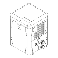
Figure 3. Minimum Clearances from Vent/Air Inlet Terminations – Indoor and Outdoor Installations
 Loading...