INSTALLATION OF INDOOR UNIT
2
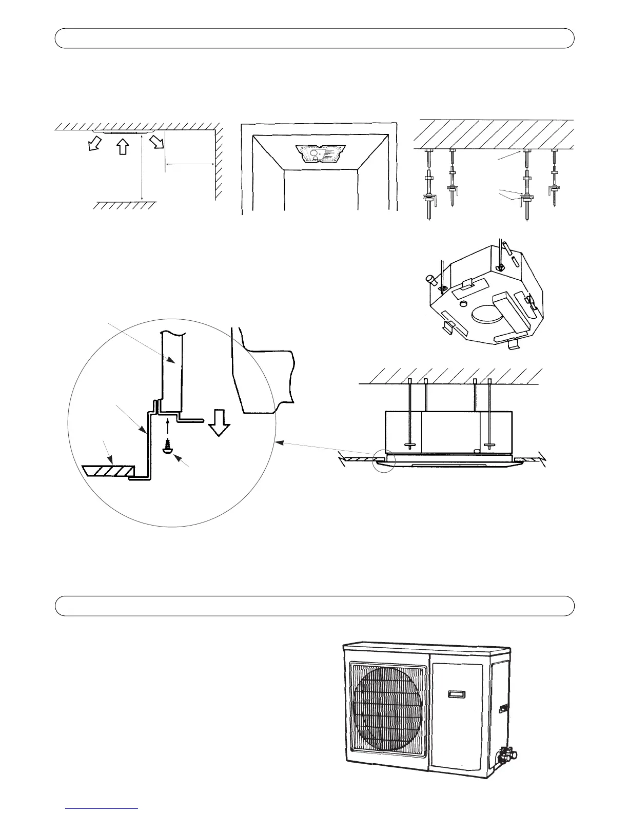
Select an installation place so that there is a clearance of at least 100 cm around the appliance (see fig.1).
Make sure that the installation does not interfere with the existent electric wiring or plumbing.
Establish the position and size of the hole in the ceiling using the external diameter of the cardboard mounting template (fig.2).
Select the final position of the indoor unit in the ceiling using the references “A-B-C-D” printed on the cardboard mounting template.
To fix the unit to the ceiling, use threaded studding and suitable anchors (fig.3).
Use a spirit level to make sure that the unit is positioned horizontally and check that it
is securely fastened to the ceiling.
fig.1 fig.2
nut
hanging
bracket
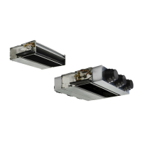
The outdoor unit should be installed on a solid wall and fastened
securely.
The following procedure must be observed before connecting the
pipes and electric cables:
· Decide which is the best position on the wall and leave enough
space to be able to carry out maintenance easily.
· Fasten the bracket to the wall using anchors which are suited
to that type of wall.
· Use a larger quantity of wall anchors than normally required
for the weight they have to bear: during operation the machine
vibrates and has to remain fastened in the same position for
years without the screws becoming loose.
INSTALLATION OF OUTDOOR UNIT
3
Fix the spacer bars in positions 1-2-3-4, following the
instructions on the cardboard mounting template.
spacer bar
air
outlet
ceiling
INDOOR UNIT
NOTE:
· Do not bend or crush the indoor unit piping. Avoid sharp bends with a radius of curvature of less than 10 cm.
· Do not bend the same part of the pipe too often: after 3 times it may become crushed.
· Do not remove the cap of the indoor unit piping until immediately before connecting the pipes.
· To prevent deformation of the air intake grille, do not overtighten the screws.
fig.3
Fix the intake gril-
le to the unit using
the screws supplie.
min. 100cm
min.
100cm