2.Replacement and Adjustment
58
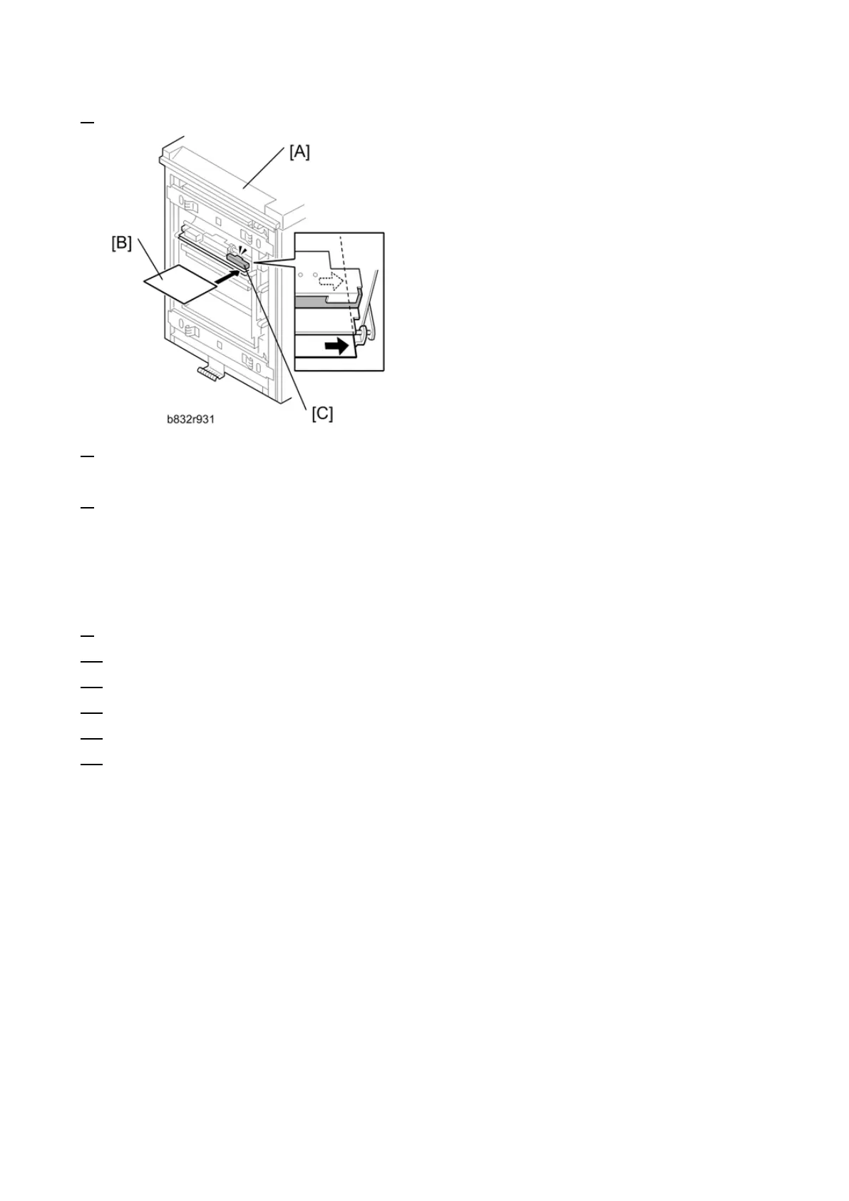
6. Make sure that the paper covers the entire area below the image position sensor (CIS) [C].
7. Enter the SP mode. Execute SP1910-002 (CIS Image Position Adjustment: LED Strength - LCT).
This calibrates the amount of light to be emitted from the CIS.
8. Execute SP1909 002 (CIS Image Position Adjustment: PWM After Adjustment - LCT).
If the displayed value is between Ah (10) and 28h (40), the CIS is calibrated successfully. (The
display is in hexadecimal code.)
If the value is outside the above range, execute SP 1910-002 and 1909-002 again. If the value
does not come between Ah and 28h, the CIS may be defective.
9. Exit the SP mode.
10. Re-attach the LCT to the main machine.
11. Select [User Tools]> [Adjust Settings for Operators].
12. Execute "0111-4 to -7" for Trays 4, 5, 6, 7 and set the value for each tray to "Off".
13. Exit from [User Tools] > [Adjust Settings for Operators] and return to the SP mode menu.
14. Adjust the image positions in the main scan direction.
Execute SP2902-003. Select Pattern 27, then print the trimming pattern.
Execute SP1002. Adjust the image position in the main scan direction for Trays 4, 5, 6, and 7.
Print the trimming pattern from each tray of the LCT and from the bypass tray (if installed).
The distance of the test pattern line from the paper edge for each tray must be 2 mm. If it is
not 2 mm, adjust with SP1002-004 to -007, depending on which tray is not within the specified
2 mm.
 Loading...