10 August, 2001 SERVICE CALL CONDITIONS
7-3
Trouble-
shooting
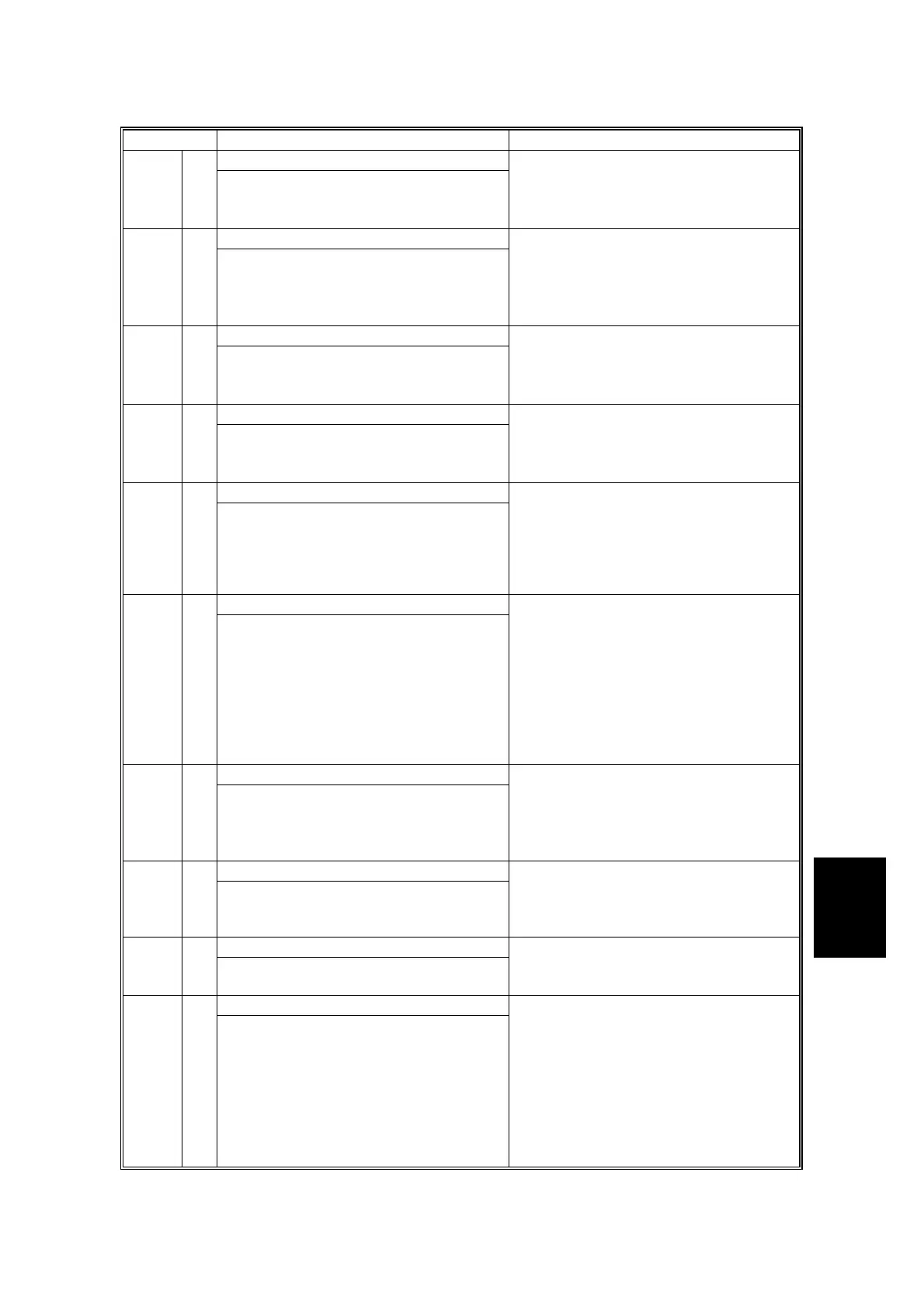
Code No. Symptom Possible Cause
DFGATE error197 B
The DFGEATE signal has already been
asserted at the original scan.
• ADF interface cable defective
• SBCU board defective
•
Mismatched firmware between the
SBCU board and ADF
Memory address error198 B
The IPU board does not receive the
memory address from the controller
board.
• Mismatched firmware between the
SBCU board and controller board
• Controller defective
• SBCU defective
•
IPU board defective
DF scanning finish error199 B
The original does not finish scanning
with in 1 minute
• ADF interface cable defective
• SBCU board defective
•
Mismatched firmware between the
SBCU board and ADF
Charge roller current leak302 B
A charge roller current leak signal is
detected.
• Charge roller damaged
• Charge high voltage supply board
defective
•
Poor connection of the PCU
Polygon motor error320 B
The polygon motor does not reach its
operating speed within 10 seconds after
the polygon motor on signal, or the lock
signal is not detected for more than 200
ms continuously during operation.
• Polygon mirror motor defective
• Poor connection between the
polygon mirror motor driver and the
SBCU board
•
SBCU board defective
Laser synchronization error322 B
The main scan synchronization detector
board cannot detect the laser
synchronization signal for more than 10
consecutive 50 ms intervals.
• Poor connection between the laser
synchronization detector board and
the SBCU board
• Laser synchronization detector board
out of position
• Laser synchronization detector board
defective
• SBCU board defective
•
LD unit defective
LD drive current over323 B
The LD drive board applies more than
100 mA to the LD.
• LD unit defective (not enough power,
due to aging)
• Poor connection between the LD unit
and the SBCU board
•
SBCU board defective
TD sensor error390 D
The TD sensor outputs less than 0.5V
or more than 4.0V 10 times
consecutively during copying.
• TD sensor abnormal
•
Poor connection of the PCU
Development bias leak391 B
A development bias leak signal is
detected.
• Poor connection of the PCU
•
High voltage supply board defective
TD sensor initial setting error392 B
TD sensor output voltage falls out of the
adjustment range (2.0 ±<> 0.2 V) after
the TD sensor initial setting has been
finished.
• Someone forgot to remove the toner
seal of the PCU
• ID sensor defective
• TD sensor abnormal
• Drum does not turn
• Development roller does not turn
• Poor connection of the PCU