19
20033283
Installation
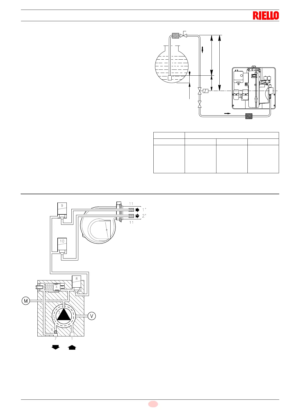
5.11.2 Single-pipe circuit
In order to obtain single-pipe working it is necessary to unscrew
the return hose, remove the by-pass screw 6)(Fig. 19) and then
screw the plug 7)(Fig. 19).
The distance “P” must not exceed 10 meters in order to avoid
subjecting the pump's seal to excessive strain; the distance "V"
must not exceed 4 meters.
For the priming pump loosen the screw 3)(Fig. 21) in order to
bleed off the air contained in the suction line and wait until the fuel
flows out.
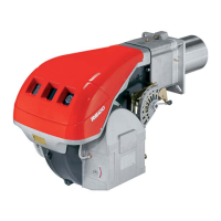
Key (Fig. 18)
H Pump/Foot valve height difference
L Piping length
ø Inside pipe diameter
1 Burner
2Pump
3Filter
4 Manual on/off valve
5 Suction line
6 Foot valve
7 Rapid closing manual valve remote controlled (only Italy)
8 On/off solenoid valve (only Italy)
11 Tank filter
Tab. G
5.12 Hydraulic system layout
Key (Fig. 19)
1 Pump suction
2 Filter
3Pump
4 Pressure governor
5 Return pipe
6 By-pass screw
7 Pump return
8 Safety solenoid
91
st
stage valve
10 2
nd
stage valve
11 Filter
M Pressure gauge
VVacuometer
+H L (meters)
(meters) ø 8 mm ø 10 mm ø 12 mm
4
3
2
1
0.5
35
30
26
21
19
90
80
69
59
53
152
152
152
130
119