20033283
20
Installation
5.13 Hydraulic connections
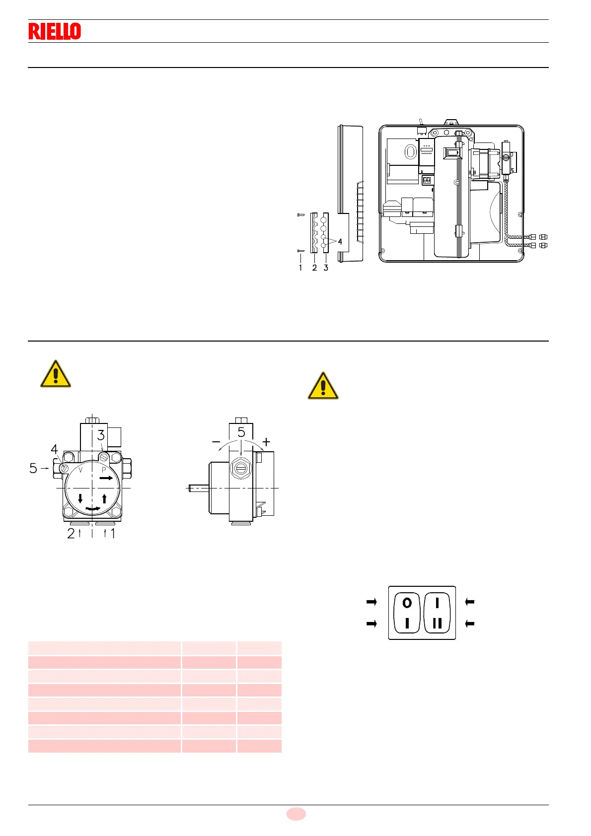
The pumps are equipped with a by-pass that connects return line
with suction line. The pumps are installed on the burner with the
by-pass closed by screw 6)(Fig. 19).
It is therefore necessary to connect both hoses to the pump.
The pump will break immediately if it is run with the return line
closed and the by-pass screw inserted.
Remove the plugs from the suction and return connections of the
pump.
Insert the hose connections with the supplied seals into the con-
nections and screw them down.
Take care that the hoses are not stretched or twisted during in-
stallation.
Route the hoses through the holes in the plate, preferably using
those on the right side, (Fig. 20):
unscrew the screws 1), now divide the insert piece into its
two parts 2) and 3) and remove the thin diaphragm blocking
the two passages 4).
Install the hoses where they cannot be stepped on or come
into contact with hot surfaces of the boiler and where they do
not hamper the opening of the burner.
Now connect the other end of the hoses to the suction and return
lines by using the supplied nipples.
5.14 Pump
1 Suction G 1/4”
2 Return G 1/4”
3 Pressure gauge attachment G 1/8”
4 Vacuum meter attachment G 1/8”
5 Pressure governor
5.14.1 Technical data
Tab. H
5.14.2 Pump priming
– Also check to make sure that the valves located on the suc-
tion line are open and that there is sufficient fuel in the tank.
– For self-priming to take place, one of the screws 3)(Fig. 21)
of the pump, must be loosened in order to bleed off the air
contained in the suction line.
– Start the burner by closing the control devices, with switch
1)(Fig. 22) in the "ON" position and with switch 22)(Fig. 5 at
page 12) in the "OIL" position.
– The pump can be considered to be primed when the gas oil
starts coming out of the screw 3)(Fig. 21). Stop the burner:
switch 1)(Fig. 22) set to "OFF" and tighten the screw 3).
The time required for this operation depends upon the diameter
and length of the suction tubing.
If the pump fails to prime at the first starting of the burner and the
burner locks out, reset the burner, and then repeat the starting
operation.
Do not illuminate the cell UV or the burner will lock out.
In case of use with gas oil containing up to 10%
Bio blend, it will be essential to use flexible oil
lines suitable for bio fuel use.
Please contact Riello for further information.
Suntec ALV65B
Min. delivery rate at 12 bar pressure kg/h 67
Delivery pressure range bar 4 - 18
Max. suction depression bar 0.45
Viscosity range mm
2
/s (cSt) 2 - 12
Max. gas oil temperature °C 60
Max. suction and return pressure bar 2
Pressure calibration in the factory bar 12
Filter mesh width mm 0.15
Before starting the burner, make sure that the
tank return line is not clogged.
Obstructions in the line could cause the seal-
ing organ located on the pump shaft to break.
(The pump leaves the factory with the by-pass
closed).
Fig. 22
Off 1
st
2
nd
12
On
Burner Stage
D469