25
20033283
Electrical system
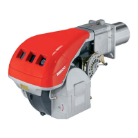
6.3 Calibration of thermal relay
This is required to avoid motor burn-out in the event of a signifi-
cant increase in power absorption caused by a missing phase.
• If the motor is star-powered, 400 V, the cursor should be po-
sitioned to "MIN".
• If the motor is delta-powered, 230 V, the cursor should be po-
sitioned to "MAX".
Even if the scale of the thermal relay does not include rated motor
absorption at 400 V, protection is still ensured in any case.
NOTE
Model RLS 50 three-phase, leaves the factory preset for
400 V power supply. If 230 V power supply is used, change
the fan motor connection from star to delta and change the
setting of the thermal cut-out as well.
The RLS 28-38-50 burners have been type- approved for
intermittent operation. This means they should compulsorily
be stopped at least once every 24 hours to enable the con-
trol box to check its own efficiency at start-up. Burner halts
are normally provided for automatically by the boiler load
control system. If this is not the case, a time switch should
be fitted in series to IN to provide for burner shut-down at
least once every 24 hours.
The RLS 28 - 38 - 50 burners are factory set for two-stage
operation and must therefore be connected to control device
TR. Alternatively, if single stage operation is required,
instead of control device TR install a jumper lead between
terminals T6 and T8 of connector X4.
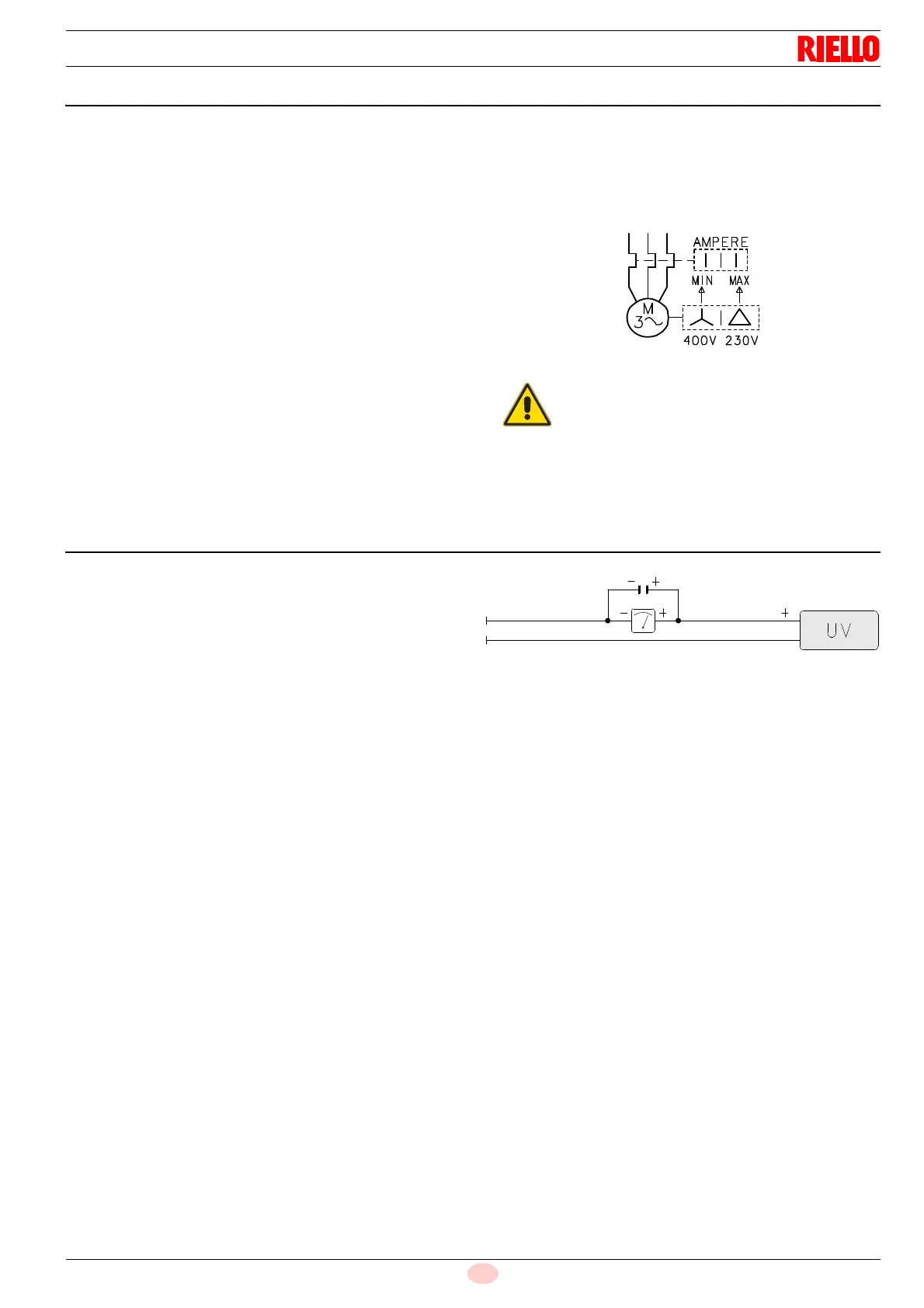
6.4 Current to the UV photocell
Min value for a good work: 70 µA.
If the value is lower, it can depend on:
– exhausted photocell
– low current (lower than 187 V)
– bad regulation of the burner
In order to measure the current, use a microammeter of 100 µA
c.c., connected to the photocell, as in the scheme, with a capac-
itor of 100 mF - 1V c.c. at the same level of the instrument.
See Fig. 28.
– Do not invert the neutral with the phase wire
in the electricity supply line. Any inversion
would cause a lockout due to firing failure.
– Only use original spare parts to replace the
components.